High-power coherent arrays of vertical cavity surface emitting lasers

Inactive Publication Date: 2005-10-25
OC ACQUISITION CORP
View PDF3 Cites 38 Cited by
  • Summary
  • Abstract
  • Description
  • Claims
  • Application Information

AI Technical Summary

Benefits of technology

[0013]Unlike previous phase locking approaches, the distribution waveguide method of the present invention can provide phase locking by controlling a precise amount of coupling between array elements independent of the element size and element spacing. A bulk beam cube, a collection of smaller distributed beam cubes, or gratings formed along the optical path, or the like, provide waveguides which collect and distribute light from / to the VCSELs, and through controlled coupling, provide a phase locking of the VCSELs.
[0014]In the coupled waveguide approach of the present invention, there is provided a linear array of elements which can be extended into a 2D array. Another major advantage of this approach is that phase adjusters can be included to assist in beam-forming and electronic beam steering. In the simplest implementation, the phase adjusters could be a VCSEL element operated below lasing threshold, where variations in current correspond to refractive index changes in the gain regions causing a change in the effective optical length of the element. This approach brings the proven technological and economic benefits demonstrated by combining transistors, capacitors, and resistors into large scale integrated circuits to integrated photonic circuits consisting of lasers, optical waveguides, and grating or other couplers.

Problems solved by technology

Each pair of DBR mirrors provides feedback to a multiple quantum well gain region, causing oscillation.

Method used


Image

  • High-power coherent arrays of vertical cavity surface emitting lasers
  • High-power coherent arrays of vertical cavity surface emitting lasers
  • High-power coherent arrays of vertical cavity surface emitting lasers

Examples


Embodiment Construction

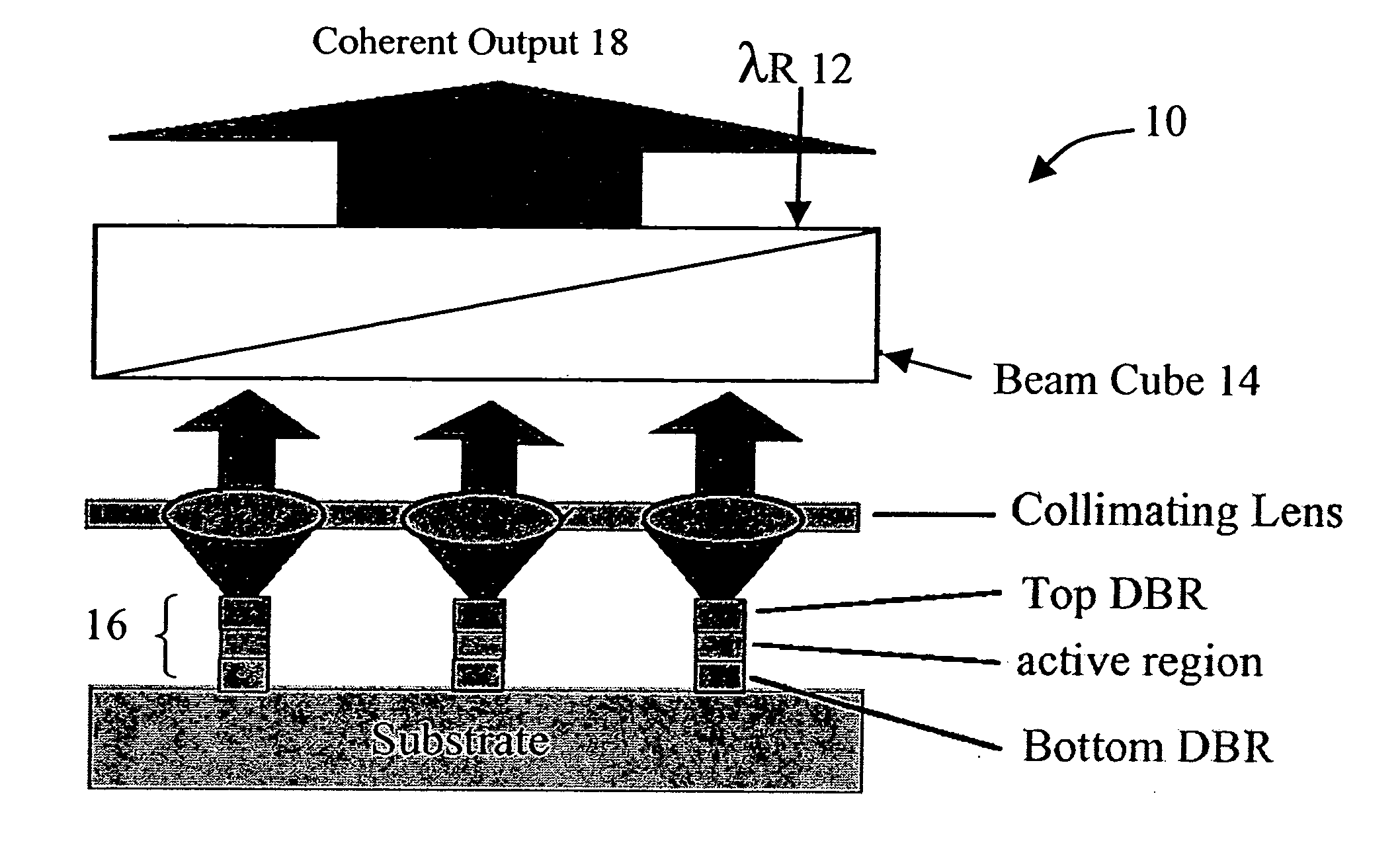
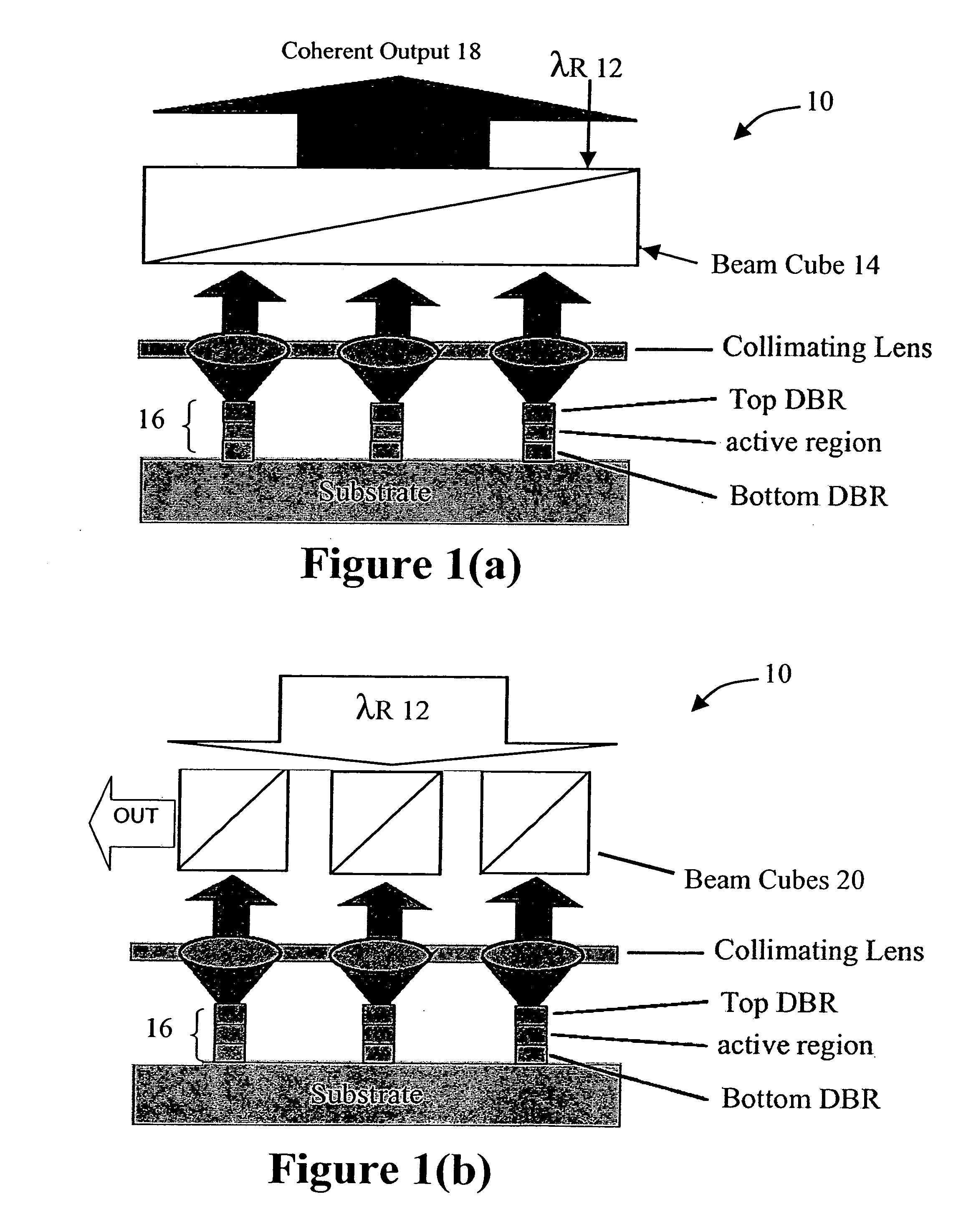
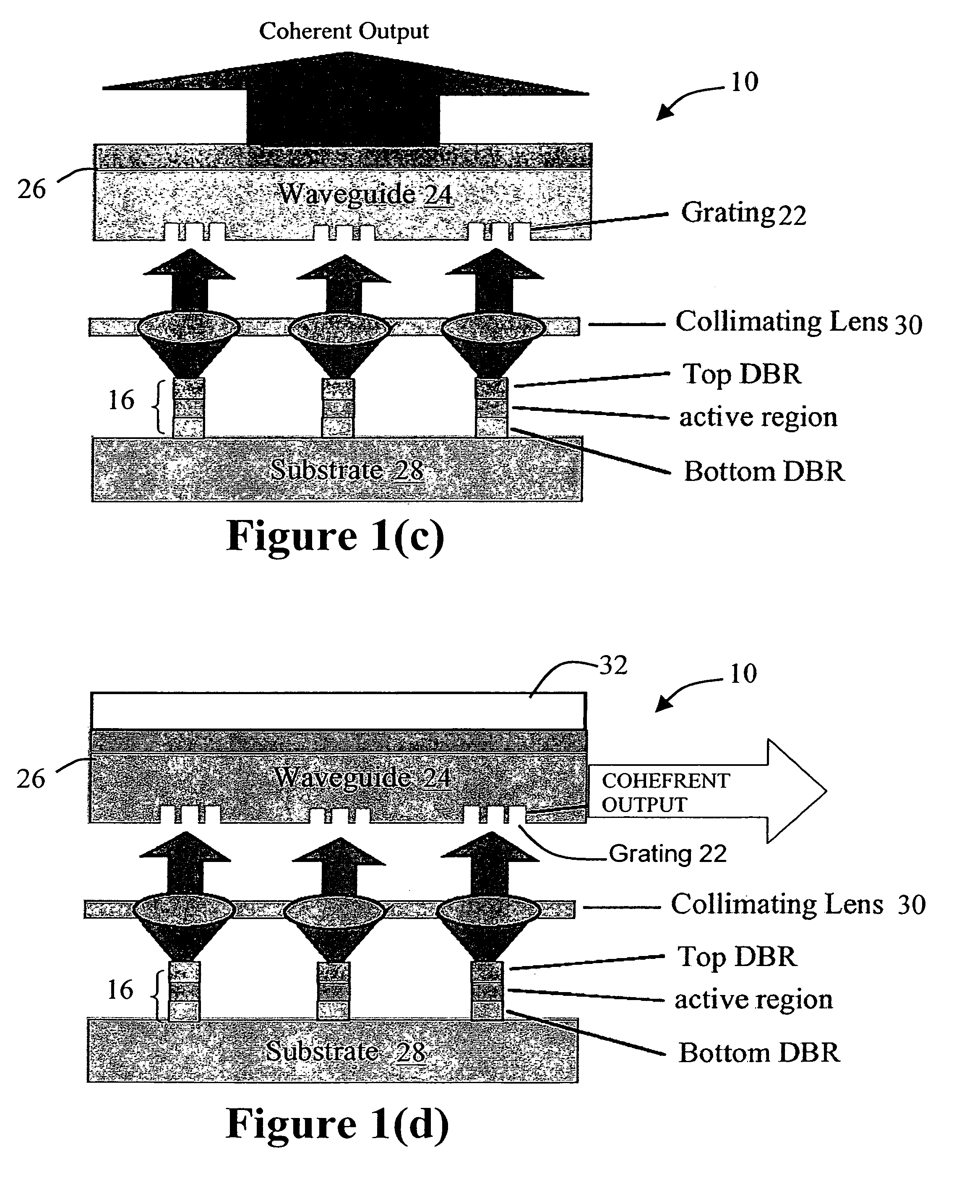
[0039]In accordance with the present invention, FIG. 1(a) illustrates a high power coherent source 10 in which a collimated reference beam 12 is passed through a beam cube 14 and illuminates an array of VCSELs 16. The beam cube 14 is designed so that the optical power coupled into each element of the VCSEL array 16 is sufficiently large such that the VCSELs will be coherently locked to the reference source 12. A vertically dependent phase is introduced to the reference beam 12 as it is passed through the beam cube 14. In order for all the VCSEL elements in the array to have the same phase and add up coherently to form a high power source, the phase difference of the reference beam between any two elements in the array should be close to a multiple of 2π radians. In order to achieve this phase front for the reference beam 12, the beam cube 14 can be rotated. The coherently summed optical outputs 18 from the VCSEL array 16 are reflected away from the reference source by the beam cube ...


PUM


Abstract

A high-power coherent array of Vertical Cavity Surface Emitter Lasers is described in which a plurality of Vertical Cavity Surface Emitting Lasers (VCSELs) are provided along with a structure which optically couples each of the VCSELs the plurality of VCSELs to one another by a predetermined amount to cause a coherent mode locking condition to occur. The coupling structure can be a beam cube, a plurality of smaller bean cubes, or a waveguide/grating system, for example. A reference source, or controlled coupling among the VCSELs, is used to phase lock the VCSELs to one another.

Description

RELATED APPLICATIONS[0001]The present application is a continuation of application Ser. No. 09 / 867,718, filed May 29, 2001, now abandoned, claims priority under 35 U.S.C. § 119(e) from provisional application Ser. No. 60 / 207,540, filed May 26, 2000.TECHNICAL FIELD[0002]The present invention is directed generally to a method and apparatus for generating high-power coherent light; and more particularly to a method and apparatus for generating high-power coherent light from arrays of vertical cavity surface emitting lasers (VCSELs).BACKGROUND ART[0003]VCSEL arrays can be used as low-cost, high-power light sources for a variety of military and commercial applications. Currently, the cost of high power (500 to 1000 W) Nd:YAG and CO2 lasers exceed $100 / Watt. Coherent VCSEL arrays have been realized in the premises network market where low power (<0.005 W), VCSEL based transceivers selling for ˜$100 dominate the market, having displaced edge-emitting semiconductor laser based transceive...

Claims


Application Information

Patent Timeline
Patent Type & Authority Patents(United States)
IPC IPC(8): H01S5/00G02B6/124G02B6/42H01S5/026H01S5/183H01S5/42
CPCG02B6/124G02B6/4296H01S5/423H01S5/4012H01S5/4062H01S5/4068
Inventor GUILFOYLE, PETEREVANS, GARY S.KO, CHENG C.
Owner OC ACQUISITION CORP
Why Eureka
Try Eureka