Nucleic acid amplification utilizing microfluidic devices

a microfluidic device and nucleic acid technology, applied in the field of microfluidic devices, can solve the problem that the flow channel of this shape cannot be formed with conventional silicon-based microfluidic devices, and achieve the effect of facilitating amplification reactions

Inactive Publication Date: 2005-11-01
CALIFORNIA INST OF TECH
View PDF145 Cites 755 Cited by
  • Summary
  • Abstract
  • Description
  • Claims
  • Application Information

AI Technical Summary

Problems solved by technology

A flow channel of this shape cannot be formed with conventional silicon-based microfluidic devices that utilize electrical current to move solutions through the microfluidic channels.

Method used


Image

  • Nucleic acid amplification utilizing microfluidic devices
  • Nucleic acid amplification utilizing microfluidic devices
  • Nucleic acid amplification utilizing microfluidic devices

Examples


example 1

[0283]This example illustrates one method of fabricating a microfluidic device comprising a rotary microfluidic channel and a temperature controller (e.g., heater).

[0284]A glass slide was gas phase treated with HMDS and Shipley SJR 574 was spun onto the glass slide. After photolithography and developing, tungsten was sputtered on the slide after removal of the photoresist (under the tungsten) with acetone. Contacts between the electrical lines running from the power supply and the heaters are made with conductive epoxy (Chemtronics, Kennesaw, Ga.).

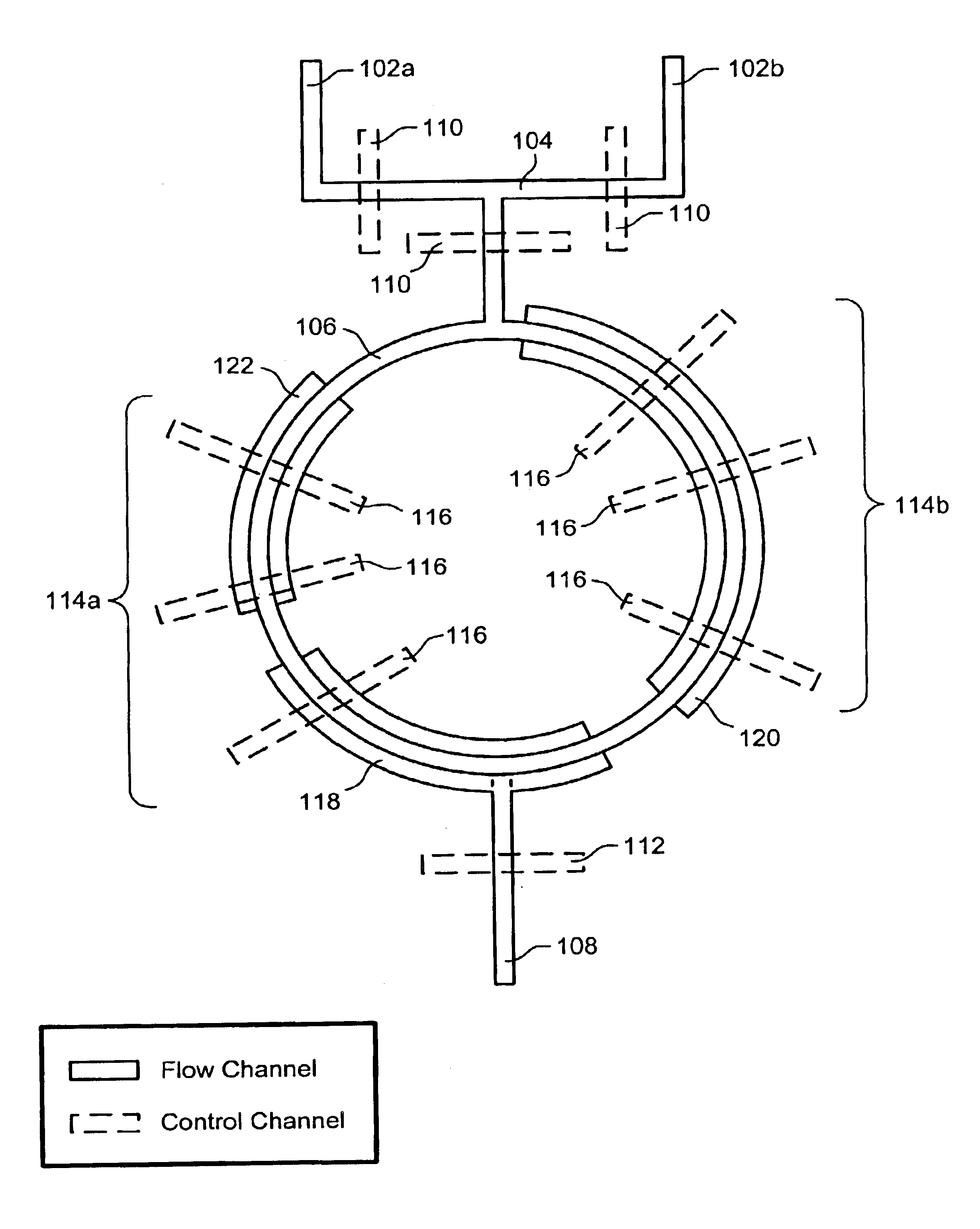
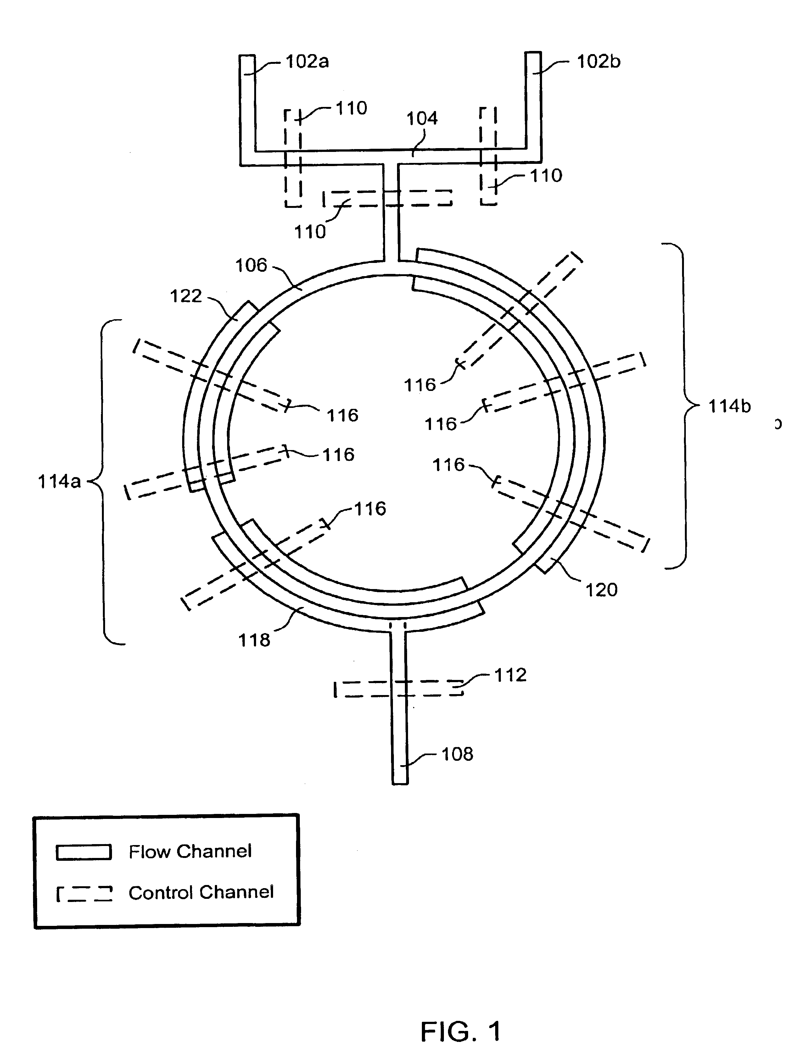
[0285]A device having the configuration shown in FIG. 1 was prepared as follows. Air and fluid mother molds (for formation of control and flow channels, respectively) were fabricated on silicon wafers by photolithography. Photoresist (Shipley SJR5740) was spun onto the silicon substrate at spin rates corresponding to the desired channel heights. After photolithography, intrusive channels made of photoresist were formed. Fluid channel molds...

example 2

[0288]This method illustrate another method of fabricating a microfluidic device comprising a rotary microfluidic channel and a temperature controller (e.g., heater).

[0289]The rotary microfluidic devices were fabricated by multilayer soft lithography techniques (Unger, M. A. et al., Science, 288:113-116 (2000); Chou, H. P. et al., Proceedings of the Solid State Sensor and Actuator Workshop, Hilton Head, S.C. (2000)). The channel pattern of the device is shown in FIG. 7A. As can be seen, the device 700 includes a circular flow channel 702 in fluid communication with an inlet 704 and an outlet 706. The flow channel 702 overlays three resistive heaters 708a, 708b and 708c, each defining a different temperature region and having a different length. S-shaped control channels 710a and 710b overlay the circular flow channel 702 to form pumps for flowing fluid through the circular flow channel 702. The control channels 712a and 712b overlaying the inlet 704 and outlet 706 serve to introduce...

example 3

[0296]This example illustrates Taqman PCR assay using the microfluidic device of Example 2 having two distinct temperature zones.

[0297]The Taqman PCR technique exploits the 5′-3′ nuclease activity of AmpliTaq Gold DNA polyrnerase to allow direct detection of PCR product by the release of a fluorescent reporter during PCR (Protocol of TaqMan PCR Reagent Kit with AmpliTaq Gold DNA Polymerase, Applied Biosystems. http: / / www.appIiedbiosystems.com. (2001)). An advantage of using this kit is that the increase in fluorescence during POR quantitatively reflects the amount of product created. The probe was an oligonucicotide containing a report dye, 6-carboxyfluorescein (FAM) in the 5′ end and a quencher dye, 6-carboxytetramethylrhodamifle, in the 3′ end. The excitation wavelength was 488 nm, while the emission wavelength of the reporter dye and quencher dye were 518 nm and 582 nm, respectively. The template, Human DNA Male, was provided with the kit. The target was portion of the β-actin ge...


PUM

PropertyMeasurementUnit
temperaturesaaaaaaaaaa

Abstract

The present invention provides microfluidic devices and methods using the same in various types of thermal cycling reactions. Certaom devices include a rotary microfluidic channel and a plurality of temperature regions at different locations along the rotary microfluidic channel at which temperature is regulated. Solution can be repeatedly passed through the temperature regions such that the solution is exposed to different temperatures. Other microfluidic devices include an array of reaction chambers formed by intersecting vertical and horizontal flow channels, with the ability to regulate temperature at the reaction chambers. The microfluidic devices can be used to conduct a number of different analyses, including various primer extension reactions and nucleic acid amplification reactions.

Description

CROSS-REFERENCE TO RELATED APPLICATIONS[0001]This application claims the benefit of U.S. Provisional Application No. 60 / 281,960, filed Apr. 6, 2001, U.S. Provisional Application No. 60 / 300,516, filed Jun. 22, 2001, and U.S. Provisional Application No. 60 / 334,473, filed Nov. 16, 2001, each of which is incorporated herein by reference in its entirety for all purposes.STATEMENT REGARDING FEDERALLY SPONSORED RESEARCH[0002]This invention was made with support from Grant Number CTS-0088649 awarded by the National Science Foundation. Therefore, the U.S. government has certain rights in this invention.FIELD OF THE INVENTION[0003]The present invention relates to microfluidic devices and methods of using the same in various types of thermal cycling reactions.BACKGROUND OF THE INVENTION[0004]Nucleic acid amplification reactions have emerged as powerful tools in a variety of genetic analyses and diagnostic applications. The value of these techniques is their ability to rapidly increase the conc...

Claims


Application Information

Patent Timeline
Patent Type & Authority Patents(United States)
IPC IPC(8): B01L3/00B01L7/00B01F13/00B01F5/00B01F5/10C12Q1/68B01F15/00B01F15/06
CPCB01F5/102C12Q3/00B01F13/0059B01L3/50273B01L3/502738B01L7/525C12Q1/6844B01F5/108B01F15/06B01L9/527B01L2300/0861B01L2300/088B01L2300/0883B01L2300/0887B01L2300/123B01L2300/1822B01L2300/1827B01L2300/1838B01L2400/0481B01L2400/0655C12Q2565/629B01F25/54B01F25/51B01F33/30B01F35/90C12Q1/68
Inventor ENZELBERGER, MARKUS M.LIU, JIANQUAKE, STEPHEN R.
Owner CALIFORNIA INST OF TECH
Why Eureka
Try Eureka