Electrically tunable on-chip resistor

a resistor and chip technology, applied in the field of resistors, can solve the problems of fixed properties and inability to change, and achieve the effect of improving the performance of the circuit incorporating the resistor

Inactive Publication Date: 2005-11-01
INT BUSINESS MASCH CORP
View PDF14 Cites 28 Cited by
  • Summary
  • Abstract
  • Description
  • Claims
  • Application Information

AI Technical Summary

Benefits of technology

[0007]According to the first embodiment, the performance of a circuit incorporating the resistor is improved because the temperature, and therefore the resistance of the resistor is controlled.

Problems solved by technology

Once a conventional resistor has been trimmed, however, its properties are fixed and cannot be changed once the semiconductor wafer carrying the circuit has been diced and packaged.

Method used


Image

  • Electrically tunable on-chip resistor
  • Electrically tunable on-chip resistor
  • Electrically tunable on-chip resistor

Examples


Embodiment Construction

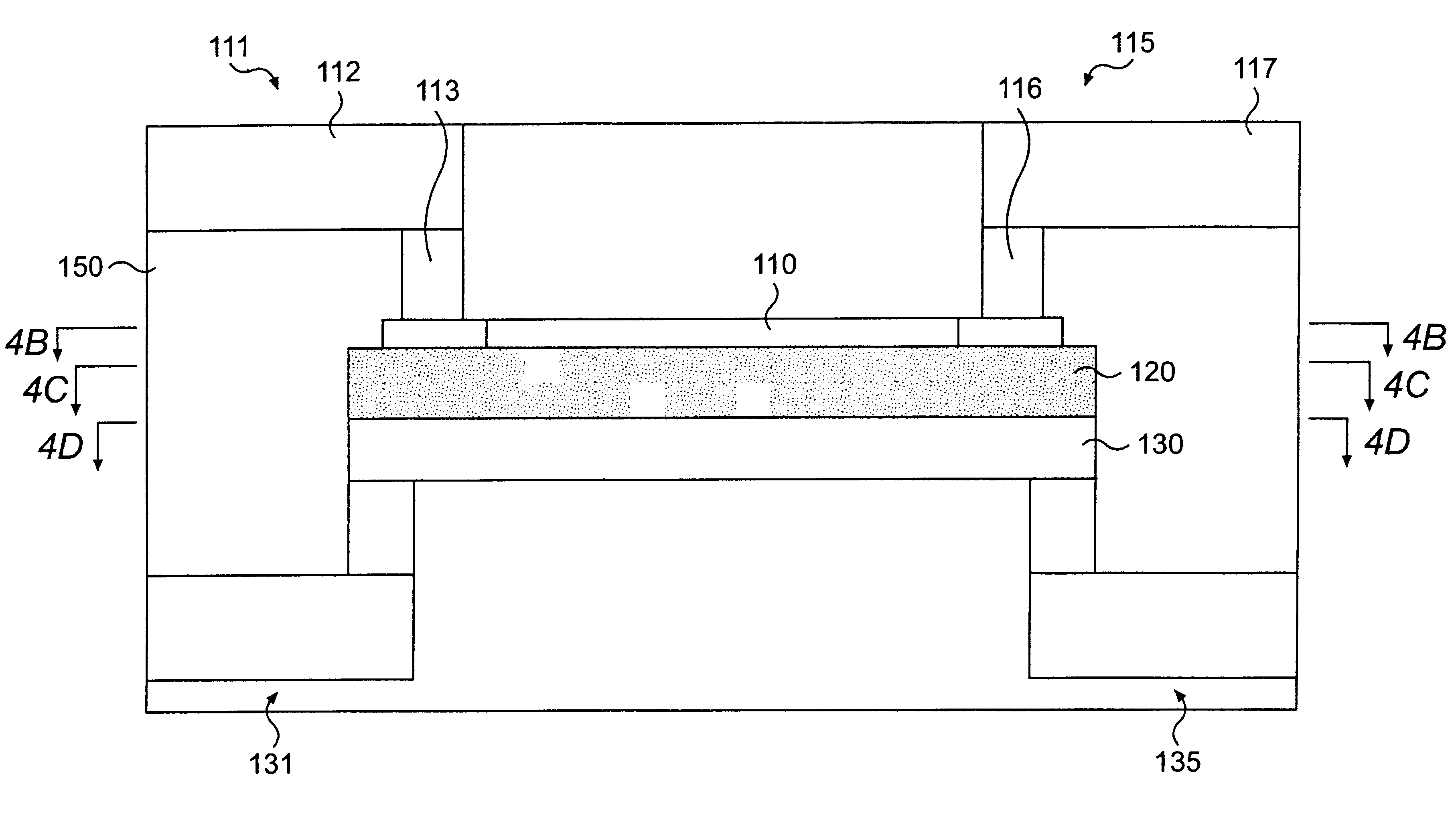
[0025]FIG. 1 is a schematic illustration of an embodiment of the invention. In FIG. 1, a resistor system 100 allows for tuning of a resistor 32. Specifically, the resistor 32 can be actively tuned while in use. The resistor system 100 may be formed on a structure such as, for example, a semiconductor chip. Other environments are also suitable.

[0026]The resistor system 100 comprises a heater driver circuit 10, a tuner 20, a resistor 32, a dielectric 34, and a heater 36. In general operation, the tuner 20 senses the resistance of the resistor 32, and determines the deviation of the sensed resistance from a nominal resistance or resistance range. The resistance range can be described as R±□R. If the resistance of the resistor 32 is outside the nominal resistance range, the tuner 20 then provides feedback to the heater driver circuit 10, which adjusts the heat output of the heater 36. The heater 36 thereby changes the temperature of the resistor 32 until the tuner 20 detects a resistanc...


PUM


Abstract

A device having a resistor and a heater disposed proximate to the resistor and capable of raising the temperature of the resistor. The device further includes a dieletric disposed between the heater and the resistor and a tuner electrically coupled to the resistor. The heater adjusts the resistance of the resistor in response to the tuner.

Description

BACKGROUND OF INVENTION[0001]1. Technical Field[0002]The technical field is resistors.[0003]2. Related Art[0004]Resistors are typically specified as having a nominal resistance, a room temperature resistance variation, and temperature coefficient of resistance. The temperature coefficient of resistance describes the variation in resistance of a resistor as a function of temperature change.[0005]Integrated circuit performance depends upon the electrical characteristics of semiconductor devices in the circuit. One method for adjusting the electrical characteristics of a semiconductor device is by “trimming” one or more resistors in the device. Trimming of resistors can be done by chemical, mechanical, and electrical means. Conventional trimming methods involve heating a resistor to change electrical and physical properties of the resistor. Once a conventional resistor has been trimmed, however, its properties are fixed and cannot be changed once the semiconductor wafer carrying the ci...

Claims


Application Information

Patent Timeline
Patent Type & Authority Patents(United States)
IPC IPC(8): H01C10/00H01L27/08
CPCH01C10/00H01L27/0802
Inventor ADKISSON, JAMES W.STAMPER, ANTHONY KENDALL
Owner INT BUSINESS MASCH CORP
Why Eureka
Try Eureka