Amorphous metal stator for a radial-flux electric motor

a technology of radial-flux electric motor and stator, which is applied in the direction of dynamo-electric machines, magnetic circuit rotating parts, and shape/form/construction of magnetic circuits, etc. it can solve the problems of long been considered unsuitable for electric motor use, tooling and manufacturing costs, and tooling wear and tear of fabrication tools and dies, so as to improve the efficiency of the motor and reduce power consumption and heat production , the effect of low core loss

Inactive Publication Date: 2005-11-01
METGLAS INC
View PDF21 Cites 72 Cited by
  • Summary
  • Abstract
  • Description
  • Claims
  • Application Information

AI Technical Summary

Benefits of technology

[0016]The stator of the invention has a core loss less than “L” when operated at an excitation frequency “f” to a peak induction level Bmax wherein L is given by the formula L=0.0074 f (Bmax)1.3+0.000282 f1.5 (Bmax) said core loss, said excitation frequency and said peak induction level being measured in watts per kilogram, hertz, and teslas, respectively. The low core loss evidenced by the stator of this invention improves the efficiency of the motor, reducing power consumption and heat production therein.

Problems solved by technology

Although amorphous metals offer superior magnetic performance when compared to non-oriented electrical steels, they have long been considered unsuitable for use in electric motors due to certain physical properties and the corresponding fabricating limitations.
For example, amorphous metals are thinner and harder than their non-oriented steel counterparts and consequently cause fabrication tools and dies to wear more rapidly.
The resulting increase in the tooling and manufacturing costs makes fabricating amorphous metal stators using such techniques commercially impractical.
The thinness of amorphous metals also translates into an increased number of laminations in the assembled stator, further increasing the total cost of an amorphous metal stator.
However, amorphous metal is a very hard material making it very difficult to cut or form easily, and once annealed to achieve peak magnetic properties, becomes very brittle.
This makes it difficult and expensive to use conventional approaches to construct an amorphous metal magnetic stator.
The brittleness of amorphous metal also causes concern for the durability of a motor or generator which utilizes amorphous metal magnetic stators.
Another problem with amorphous metal magnetic stators is that the magnetic permeability of amorphous metal material is reduced when it is subjected to physical stresses.
As an amorphous metal magnetic stator is subjected to stresses, the efficiency at which the core directs or focuses magnetic flux is reduced resulting in higher magnetic losses, reduced efficiency, increased heat production, and reduced power.
While this approach produces an efficient motor, the large air gap between the stator and rotor limits the performance and control of the motor.
This greatly increases the reluctance of the magnetic circuit and the electric current required to operate the motor.
Although this method permits fabrication of complex stator shapes, the structure contains numerous air gaps between the discreet flake particles of amorphous metal.
This will greatly increase the reluctance of the magnetic circuit and the electric current required to operate the motor.
A non-magnetic material is inserted into the joints between the wound pieces and pole pieces, increasing the gap, and thus the reluctance of the magnetic circuit and the electric current required to operate the motor.
This configuration further increases the reluctance of the stator, because contiguous layers of the wound pieces and of the pole pieces meet only at points, not along full line segments, at the joints between their respective faces.
Even small sections of recrystallized amorphous metal will increase the magnetic losses in the stator.
The mechanical stresses imparted on the laminated strips during the shaping operation will increase the core loss of the finished stator.
This approach does not envision annealing of the stator to relieve the mechanical stresses.
This will greatly increase the reluctance of the magnetic circuit and the electric current required to operate the motor.

Method used


Image

  • Amorphous metal stator for a radial-flux electric motor
  • Amorphous metal stator for a radial-flux electric motor
  • Amorphous metal stator for a radial-flux electric motor

Examples


example 1

Preparation and Electro-Magnetic Testing of an Amorphous Metal Stator

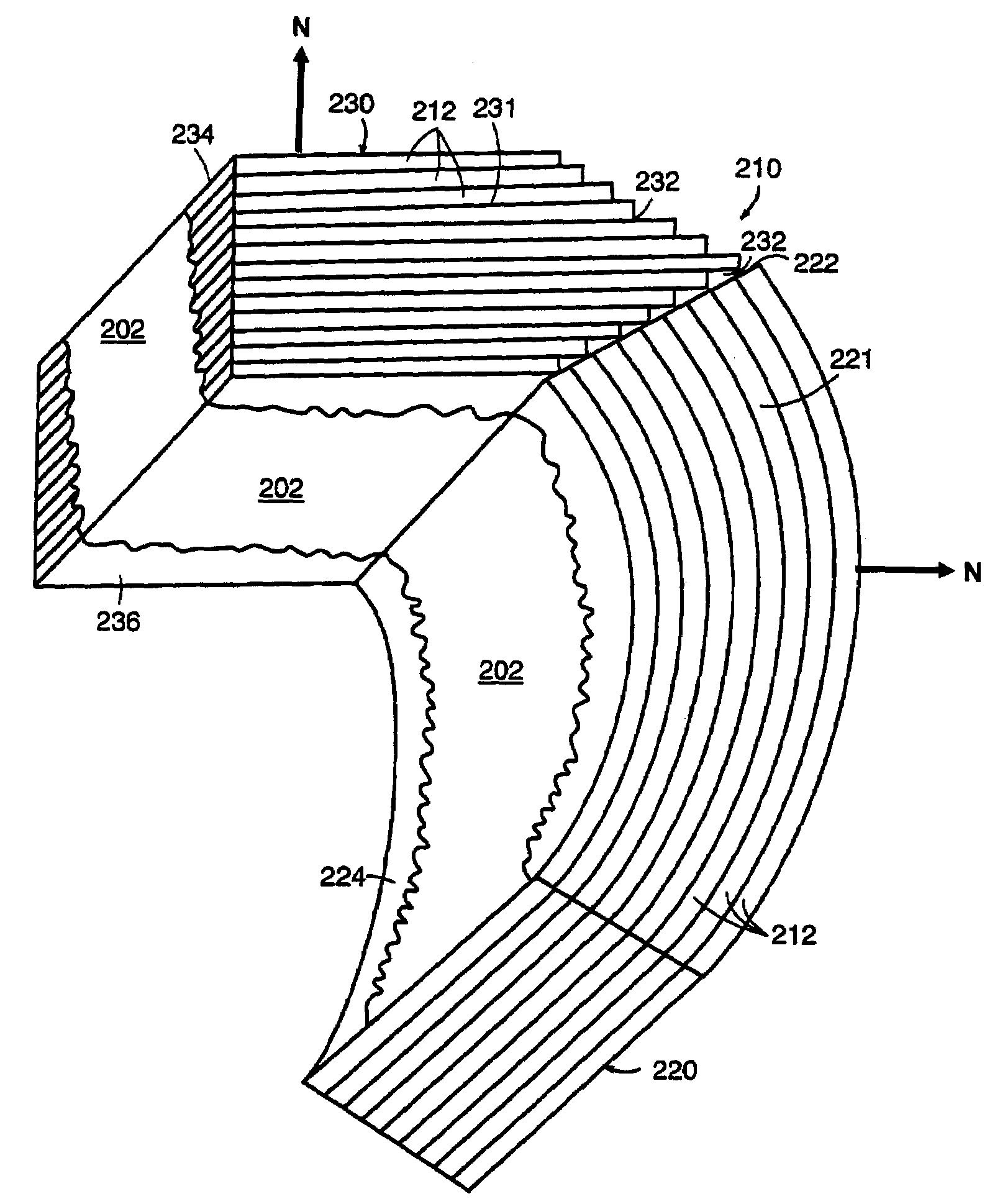
[0066]Fe80B11Si9 amorphous metal ribbon, approximately 60 mm wide and 0.022 mm thick, is wrapped around a rectangular mandrel or bobbin having dimensions of approximately 25 mm by 90 mm. Approximately 800 wraps of amorphous metal ribbon are wound around the mandrel or bobbin producing a rectangular core form having inner dimensions of approximately 25 mm by 90 mm and a build thickness of approximately 20 mm. The core / bobbin assembly is annealed in a nitrogen atmosphere. The anneal consists of: 1) heating the assembly up to 365° C.; 2) holding the temperature at approximately 365° C. for approximately 2 hours; and, 3) cooling the assembly to ambient temperature. The rectangular, wound, amorphous metal core is removed from the core / bobbin assembly. The core is vacuum impregnated with an epoxy resin solution. The bobbin is replaced, and the rebuilt, impregnated core / bobbin assembly is cured at 120° C. for approximate...

example 2

High Frequency Behavior of a Low-Loss Amorphous Metal Stator

[0074]The core loss data taken in Example 1 above are analyzed using conventional non-linear regression methods. It is determined that the core loss of a low-loss amorphous metal stator comprised of Fe80B11Si9 amorphous metal ribbon could be essentially defined by a function having the form

[0075]selected to define an upper bound to the magnetic losses of the amorphous metal stator. Table 5 recites the measured losses of the stator segment in Example 1 and the losses predicted by the above formula, each measured in watts per kilogram. The predicted losses as a function of f (Hz) and Bmax (Tesla) are calculated using the coefficients c1=0.0074 and c2=0.000282 and the exponents n=1.3, m=2.4, and q=1.5. The measured loss of the amorphous metal stator segment of Example 1 is less than the corresponding loss predicted by the formula.

[0076]

TABLE 5Measured CorePredictedBmaxFrequencyLossCore LossPoint(Tesla)(Hz)(W / kg)(W / kg)10.3600.1...

example 3

Preparation and Electro-Magnetic Testing of a Nanocrystalline Alloy Stator

[0077]Fe73.5Cu1Nb3B9Si1,2,3 amorphous metal ribbon, approximately 25 mm wide and 0.018 mm thick, is wrapped around a rectangular mandrel or bobbin having dimensions of approximately 25 mm by 90 mm. Approximately 1000 wraps of amorphous metal ribbon are wound around the mandrel or bobbin producing a rectangular core form having inner dimensions of approximately 25 mm by 90 mm and a build thickness of approximately 20 mm. The core / bobbin assembly is annealed in a nitrogen atmosphere. The anneal is carried out by performing the following steps: 1) healing the assembly up to 580° C.; 2) holding the temperature at approximately 580° C. for approximately 1 hour; and, 3) cooling the assembly to ambient temperature. The assembly is vacuum impregnated with an epoxy resin solution and cured at 120° C. for approximately 4.5 hours. When fully cured, the corn is removed from the core / bobbin assembly. The resulting stacked,...


PUM


Abstract

An amorphous metal stator for a high efficiency radial-flux electric motor has a plurality of segments, each of which includes a plurality of layers of amorphous metal strips. The plural segments are arranged to form a generally cylindrical stator having a plurality of teeth sections or poles protruding radially inward from the inner surface of the stator. In a first embodiment, the stator back-iron and teeth are constructed such that radial flux passing through the stator crosses just one air gap when traversing each segment of the stator. In a second embodiment, the stator back-iron and teeth are constructed such that radial flux passing through the stator traverses each segment without crossing an air gap.

Description

CROSS-REFERENCE TO RELATED APPLICATION[0001]This application is a Continuation-in-Part of application Ser. No. 09 / 099,786, filed Jun. 18, 1998, entitled “Amorphous Metal Stator For A Radial-Flux Electric Motor.”BACKGROUND OF THE INVENTION[0002]1. Field of the Invention[0003]This invention relates to a stator for an electric motor; and more particularly, to an amorphous metal stator for a high efficiency radial-flux electric motor.[0004]2. Description of the Prior Art[0005]A radial-flux design electric motor typically contains a generally cylindrical stator made from a plurality of stacked laminations of non-oriented, electrical steel. Each lamination has the shape of a circular washer having “teeth” that form the poles of the stator. The teeth protrude from the inner diameter of the stacked laminations and point toward the center of the cylindrical stator. Each lamination is typically formed by stamping, punching or cutting the mechanically soft, non-oriented electrical steel into t...

Claims


Application Information

Patent Timeline
Patent Type & Authority Patents(United States)
IPC IPC(8): H02K1/12H02K1/14H02K15/02
CPCH02K1/148H02K15/022
Inventor DECRISTOFARO, NICHOLAS J.NGO, DUNG A.BYE, JR., RICHARD L.STAMATIS, PETER J.FISH, GORDON E.
Owner METGLAS INC
Why Eureka
Try Eureka