
Method for making a stem web

a technology of stems and webs, applied in the direction of surface layering apparatus, cloth making apparatus, manufacturing tools, etc., can solve the problem of not being easily adaptable to meet different applications and purposes, and achieve the effect of improving the mechanical fastening

Inactive Publication Date: 2005-11-08
3M INNOVATIVE PROPERTIES CO
View PDF43 Cites 24 Cited by
  • Summary
  • Abstract
  • Description
  • Claims
  • Application Information

AI Technical Summary

Benefits of technology

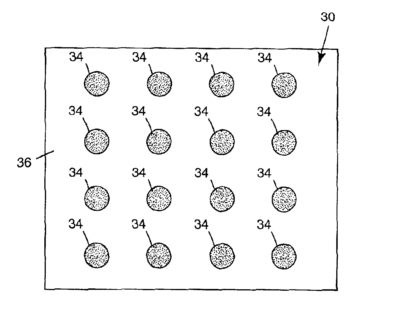
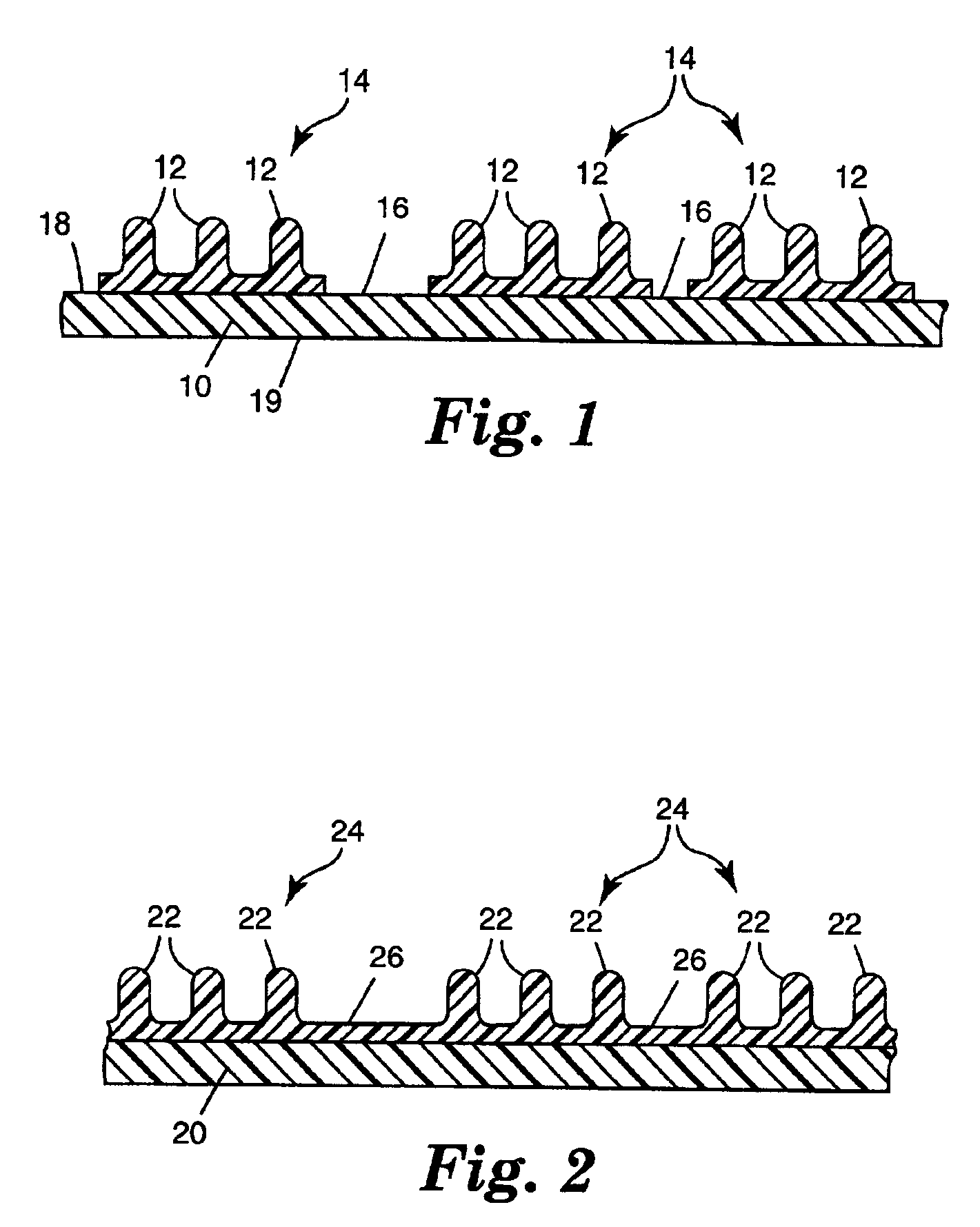
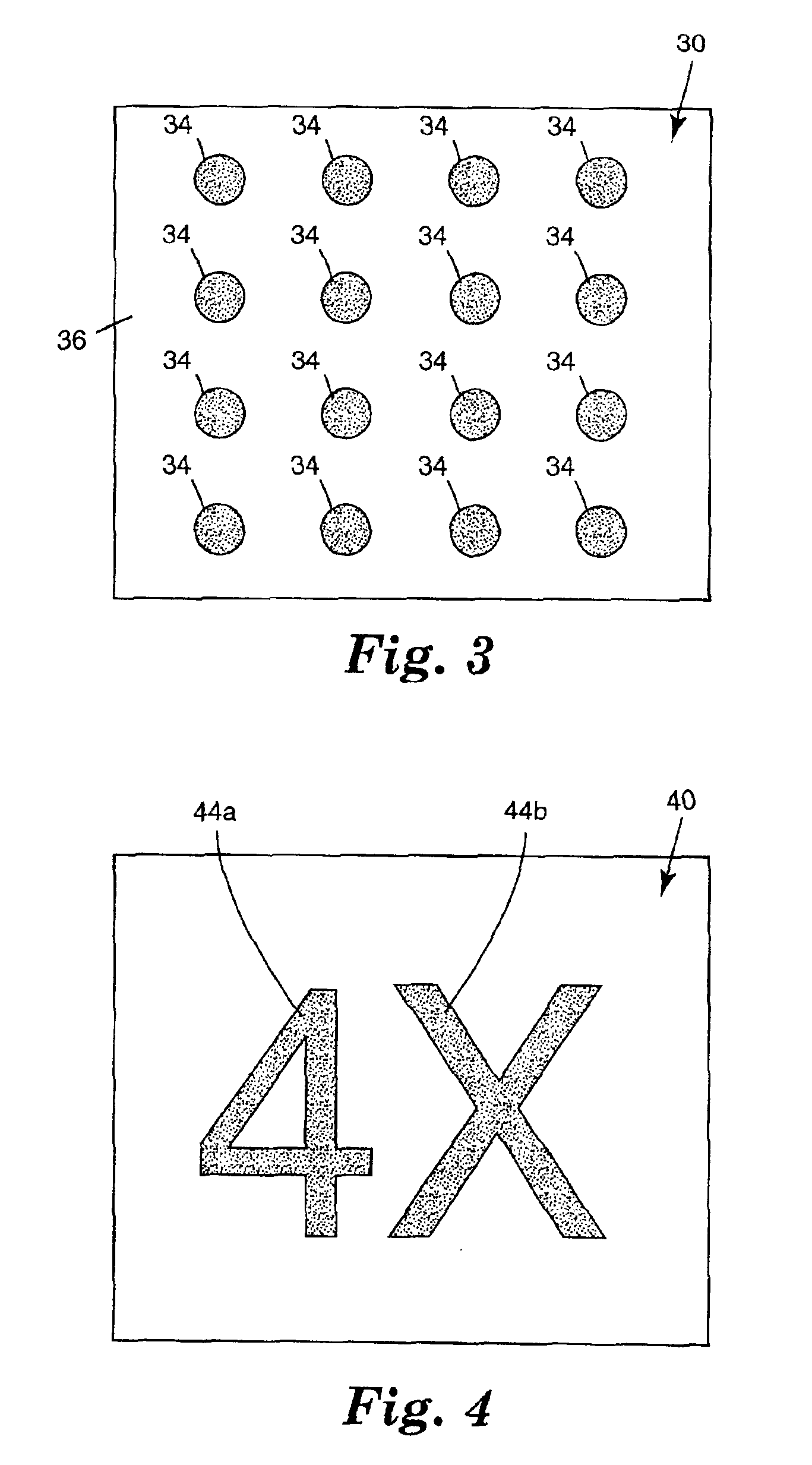
[0006]The present invention relates to a web of material having at least two major sides. The web includes a plurality of discrete regions on at least a first major side, with a plurality of stems extending from each discrete region. The plurality of stems are fused and formed to at least the first major side of the web. The stems can be configured for use as a mechanical fastener, and may have one or more different configurations and orientations. For example, the stems may have a hook formation suitable for interlocking with another hook or with a loop. Alternatively, the stems may be substantially mushroom-shaped. The stems may be oriented perpendicular to the web, or may be oriented at an angle of less than 90 degrees to the web. In one embodiment, the web defines a localized plane, and the plurality of stems are oriented at multiple angles to the localized plane. At such angles, the stems provide an improved mechanical fastening effect when a force is applied parallel to the localized plane and against the angled stems. In certain embodiments, at least a portion of the web is configured and arranged to engage the plurality of stems.

Problems solved by technology

Although these patents disclose acceptable stemmed webs, they may not be readily adapted to meet different applications and purposes.

Method used


Image

  • Method for making a stem web
  • Method for making a stem web
  • Method for making a stem web

Examples


examples 1 and 2

[0047]Examples 1 and 2 demonstrate using breathable elastic substrates and bi-directional stem configurations.

[0048]In Example 1, Substrate A, an elastic breathable substrate, was first made as follows. A blown micro-fiber pressure sensitive adhesive (BMF-PSA) web made of HL-8156 block copolymer pressure sensitive adhesive ITSA) (HB Fuller Company, St. Paul, Minn.) was prepared by processing the solid adhesive through a grid melt system (J&M Laboratories, Inc. Dawsonville, Ga.) and then through a 30.5-cm wide blown microfiber (BMF) die at a rate of 2.0 kg / hr. The grid melt system had a hopper holding capacity of 40 kg and a melting capacity of 40 kg / hr. The melt pump volume was 1.68 cc / rev and the process temperature was 135° C. The BMF-PSA was discharged from a melt blowing die having circular smooth surface orifices (8 / cm) positioned approximately 10 cm above a vertical nip point formed by two 40.6-cm wide silicone coated rolls.

[0049]A layer of polypropylene spunbond nonwoven mate...

examples 3-5

[0054]Examples 3-5 demonstrate constructions having alternate shapes of stem regions. Examples 3-5 have stem regions that are continuous in the cross-web direction and are substantially perpendicular to the down-web direction of the web.

[0055]Example 3 was made in a manner similar to Example 1 and with the same substrate as Example 1. However, the stem formable material was deposited using a small orifice die tip with a single row of circular smooth surface orifices (8 / cm) rather than bead tip nozzles. The small orifice die tip had circular smooth surface orifices (8 / cm) with 0.51 mm diameter. The stem formable material was deposited at a rate of 0.7 kg / hr.

[0056]The resulting stem-surfaced regions were cross direction stripes approximately 0.5 cm wide and separated approximately 2 cm from each other. Each region had on average approximately 8 stems across its width and 16 rows / cm cross web. The webs were very ductile and breathable, and fastened to themselves when wrapped in either ...

example 6

[0059]Example 6 demonstrated a construction having an inelastic substrate and another process of making discrete regions of stem formable material.

[0060]A stem formable material, Monthane™ 440, was passed through a glue gun (available as PAM 600 Spraymatic™ from Fastening Technology, Inc, Charlotte, N.C.). The circular exit of the glue gun was approximately 1.5 mm diameter and the process temperature was about 232° C. The molten material was discharged from the gun in discrete amounts as the gun was repeatedly triggered on and off at a frequency of 1.0 pulse per second. The discrete amounts or spots of material were deposited directly onto Substrate B. The web was then conveyed approximately 20 cm into a vertical nip point formed by two 40.6-cm wide silicone coated rolls at a speed of 4.6 m / min. The nip force was 1.7 kN across a 30.5 cm wide web. The first roll had a tooled surface that contained cavities with diameters of about 0.25 mm, depths in excess of about 0.80 mm and spacing...


PUM

PropertyMeasurementUnit
Fractionaaaaaaaaaa
Fractionaaaaaaaaaa
Fractionaaaaaaaaaa

Abstract

Method for making a stem web material having a plurality of stems extending from discrete regions (patches or stripes) of the web, comprising:a) providing a web (e.g. nonwoven, woven or knit textile fabric; paper; microporous membrane, polymer film; etc.);b) providing discrete quantities of a polymer at a temperature above its softening point or in molten state;c) fusing the discrete quantities of polymer to the web; andd) forming a plurality of stems in each of the discrete quantities of polymer material.The stems can be formed by pressing the web on which the patches or stripes of polymer are deposited against a tool having a surface with a plurality of stem-forming holes. The stems can be given enlarged ends by bringing the surface of the stem web close to a heated surface.

Description

[0001]This is a divisional of application Ser. No. 09 / 257,447 filed Feb. 25, 1999, now abandoned.TECHNICAL FIELD[0002]The present invention is directed to stemmed web constructions useful as mechanical fasteners. More particularly, the invention relates to web constructions having discrete regions of stems, and methods of making the same.BACKGROUND OF THE INVENTION[0003]Stemmed webs, such as hook and loop fasteners, have been in use for a number of years. These webs typically include stems that are secured to the web. The stems are commonly formed into hooks configured to interlock with a loop material. In this description, small protrusions capable of engaging small loops or mesh of, for example, fabric or polymer will be referred to as hooks whether they are actually in the shape of hooks or other shapes. A common form of hook is mushroom-shaped and can also be used as a mechanical fastener to engage other hooks.[0004]U.S. Pat. Nos. 4,056,593, 4,959,265, and 5,077,870 disclose met...

Claims


Application Information

Patent Timeline
IPC IPC(8): A44B18/00B29C43/22B32B5/26B32B5/22D04H13/00
CPCA44B18/0003A44B18/0046B29C43/222B32B5/26D04H13/006D04H13/007Y10T428/24182Y10T156/1077Y10T428/24802Y10T156/1089Y10T156/1064Y10T428/24008Y10T156/1062B32B37/24
Inventor TUMAN, SCOTT J.SEIDEL, DAVID L.LEVITT, LEONBERG, BRANDON T.
Owner 3M INNOVATIVE PROPERTIES CO
Learn More