Combustion control apparatus for an engine

a combustion control and engine technology, applied in mechanical devices, electric control, machines/engines, etc., can solve the problems of reducing the amount of oxygen in the intake air, nox and soot being produced by oxygen shortage, and it is difficult to reduce both nox and soot simultaneously during diesel combustion, so as to improve fuel efficiency

Inactive Publication Date: 2005-11-15
MAZDA MOTOR CORP
View PDF36 Cites 40 Cited by
  • Summary
  • Abstract
  • Description
  • Claims
  • Application Information

AI Technical Summary

Benefits of technology

[0018]An object of present invention is to optimize ignition timing of a premixture and to improve fuel efficiency, even when the recirculation ratio of the exhaust gas is greatly changed or when the temperature of the exhaust gas and other factors fluctuate by the change in the engine operation. Therefore, ...

Problems solved by technology

Moreover, soot is produced by the shortage of oxygen at the portion where the fuel is unduly rich.
During such EGR, the recirculation of the inactive exhaust gas decreases the combustion temperature to suppress the generation of NOx, but on the other hand, reduces the amount of oxygen in the intake air.
Thus, a large amount of EGR results in the promotion of soot production.
That is, because of the trade-off relationship between the reductions in NOx and soot, it is actually difficult to decrease both NOx and soot simultaneously during diesel combustion.
Thus, for example, in the case of an increase in the flow amount of intake air caused by a rise in engine rotational speed, the recirculation amount changes after a lag time, which causes a problem wherein the EGR ratio is temporarily lowered so as to deviate from the proper range.
Furthermore, even with the same EGR ratio, the change in temperature condition of the recirculating exhaust gas causes the ignition delay time to vary.
In addition, the change in temperatur...

Method used


Image

  • Combustion control apparatus for an engine
  • Combustion control apparatus for an engine
  • Combustion control apparatus for an engine

Examples


Embodiment Construction

[0058]Preferred embodiments of the present invention will be described with reference to the accompanying drawings.

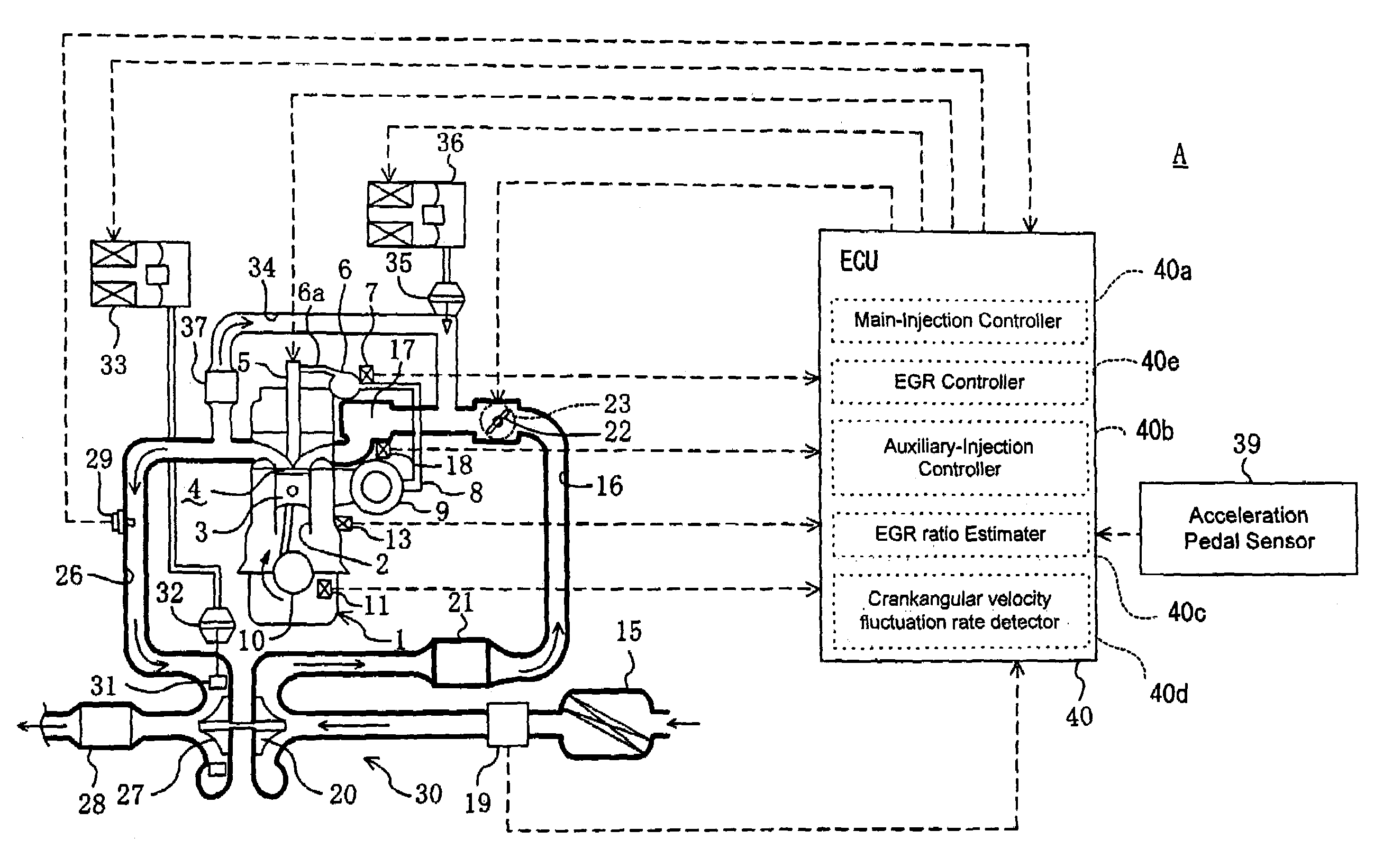
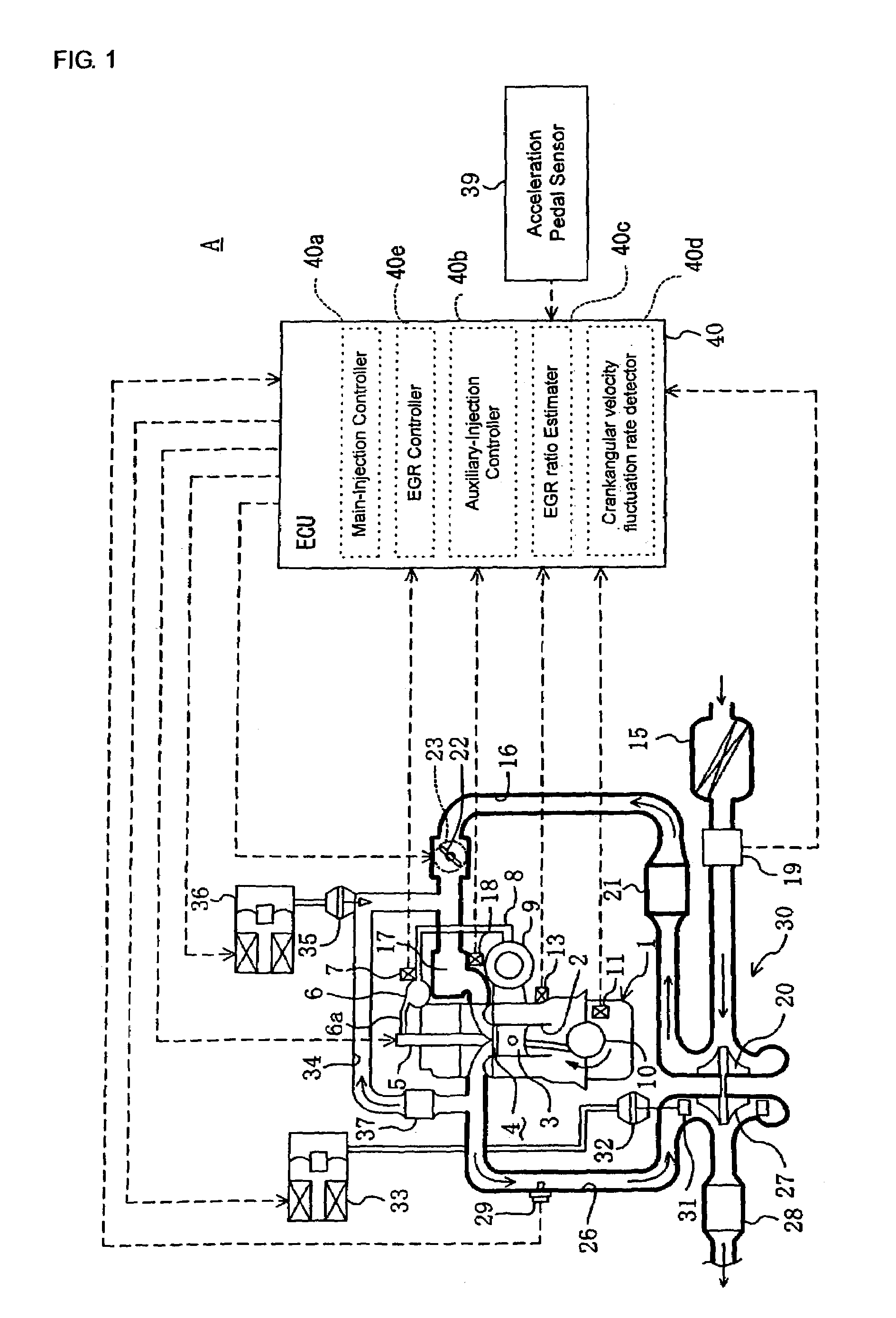
[0059]FIG. 1 illustrates a configuration of a combustion control apparatus A for an engine in accordance with a preferred embodiment of the present invention. Identified by reference numeral 1 is diesel engine mounted in a vehicle. The engine 1 comprises a plurality of cylinders 2 only one of which is illustrated for convenience. A piston 3 is fitted within each cylinder 2, so as to reciprocate in a vertical direction, respectively. The piston 3 defines a combustion chamber 4 within each cylinder 2. An injector 5 (fuel injection valve) is arranged at a roof of the combustion chamber 4. The injector 5 injects fuel at high pressure directly into the combustion chamber 4 from injection bores at the tip of the injector 5. The proximal end of the injector 5 for each cylinder 2 is connected to a common fuel delivery pipe 6 (a common rail) via fuel delivery pipes 6a only one o...


PUM


Abstract

To optimize an ignition timing of premixture for improving fuel efficiency regardless of significant change in an EGR ratio or a fluctuation in temperature of recirculated exhaust gas and temperature in a combustion chamber, there is provided a control apparatus for a diesel engine which controls an injector extending into the combustion chamber to execute a main-injection for injecting fuel and increasing the EGR ratio, so as to attain the premixed compressive ignition combustion while the engine is in the premixed combustion region on the low load side. Just before or after a cool flame reaction occurs in the mixture formed by the main-injection, an auxiliary-injection is executed so that the latent heat of vaporization of the fuel decreases the temperature of the mixture to delay the ignition to a timing near TDC. The auxiliary-injection amount is adjusted according to the estimated value of EGR ratio or the change in the crank angular velocity to optimize the ignition timing of the mixture.

Description

BACKGROUND OF THE INVENTION[0001]1. Field of the Invention[0002]The present invention relates to a combustion control apparatus for an engine, and more particularly to ignition timing control for performing fuel injection by directly injecting fuel into the combustion chamber in a cylinder with an injector, so as to generate a premixed air-fuel mixture which causes self ignition by compression.[0003]2. Description of the Related Art[0004]Generally, a direct-injection diesel engine injects fuel into a combustion chamber at a high temperature and high pressure near the top-dead-center position of a compression stroke in a cylinder so as to cause self ignition of the fuel. At this time, the fuel injected into the combustion chamber progresses while being split into fine droplets (atomized) by collision with highly dense air, so as to form an approximately cone-shaped fuel spray. The fuel droplets vaporize from its surface and involve surrounding air mainly at the leading edge and its p...

Claims


Application Information

Patent Timeline
IPC IPC(8): F02D21/00F02D35/02F02D21/08F02B1/12F02D41/40F02B1/00F02D41/30F02M25/07F02D23/00F02B29/04F02B29/00F02B75/02
CPCF02B1/12F02D41/0057F02D41/3035F02D41/402F02M25/0707F02M25/0727F02M25/0738F02B29/0406F02B29/0493F02B75/02F02B2275/14F02D23/00F02D35/02F02D41/0072F02D41/3047F02M25/0713F02M25/0777Y02T10/44Y02T10/123Y02T10/47F02M26/05F02M26/10F02M26/23F02M26/33F02M26/57Y02T10/12Y02T10/40
Inventor KATAOKA, MOTOSHITERAZAWA, YASUYUKIHAYASHIBARA, HIROSHISAITO, TOMOAKI
Owner MAZDA MOTOR CORP
Why Eureka
Try Eureka