Combined cycle for generating electric power

a combined cycle and electric power technology, applied in the direction of machines/engines, biofuels, mechanical equipment, etc., can solve the problems of undesirable sulfur in product gas, and achieve the effect of increasing the fuel to power efficiency of the combined cycle and reducing the cos

Inactive Publication Date: 2005-11-22
WYLIE INVENTIONS
View PDF11 Cites 39 Cited by
  • Summary
  • Abstract
  • Description
  • Claims
  • Application Information

AI Technical Summary

Benefits of technology

[0019]The integration of the gasification plant with a combined cycle and the several heat integration concepts of the present invention, which are taught herein, reduce the cost and increase the fuel to power efficiency of the combined cycle; this will become evident as the invention is described.

Problems solved by technology

Also, supplemental firing is used when sensible heat available from the gas turbine exhaust gas stream is not adequate to raise all the steam required for the steam turbine train.
Sulfur in the product gas is undesirable because it is converted to sulfur oxides when the gas is burned and sulfur oxides are of course unacceptable air pollutants.

Method used


Image

  • Combined cycle for generating electric power
  • Combined cycle for generating electric power
  • Combined cycle for generating electric power

Examples


Embodiment Construction

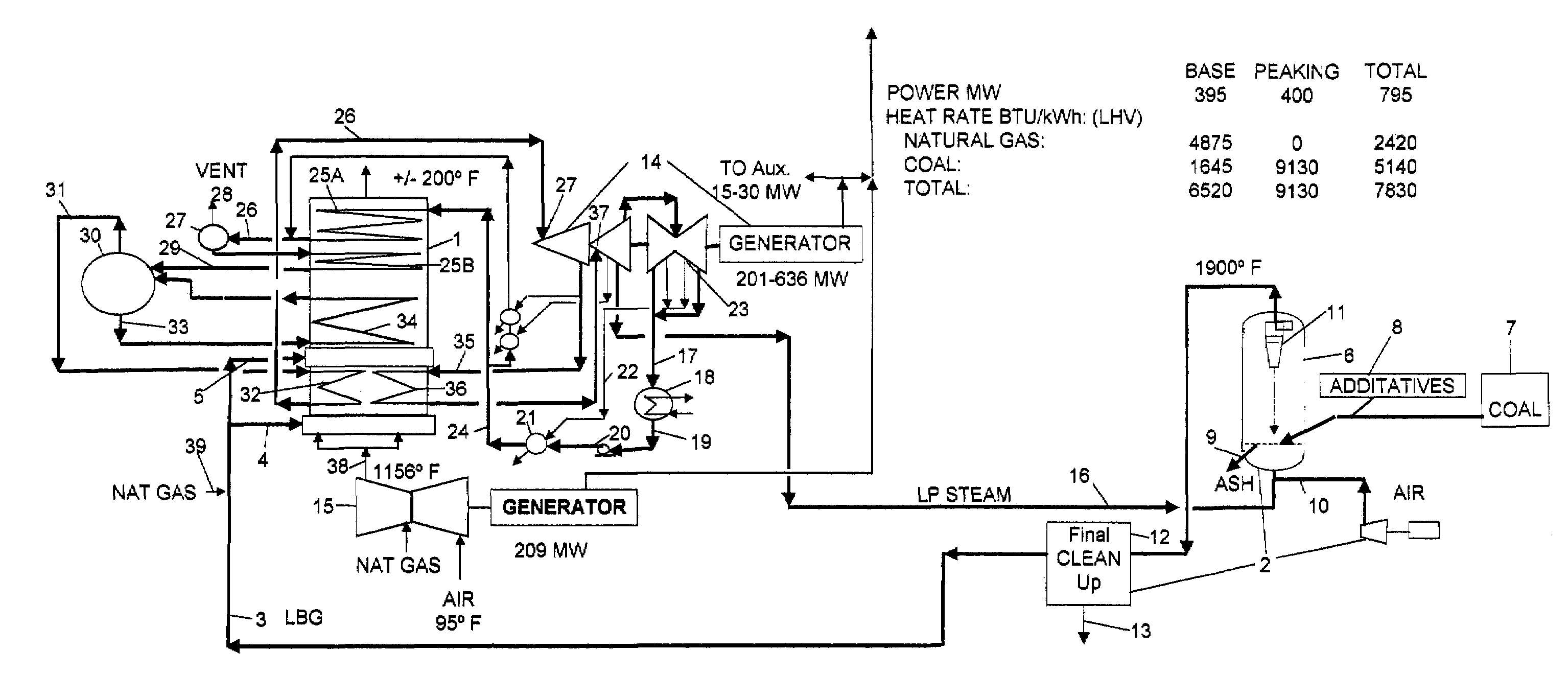
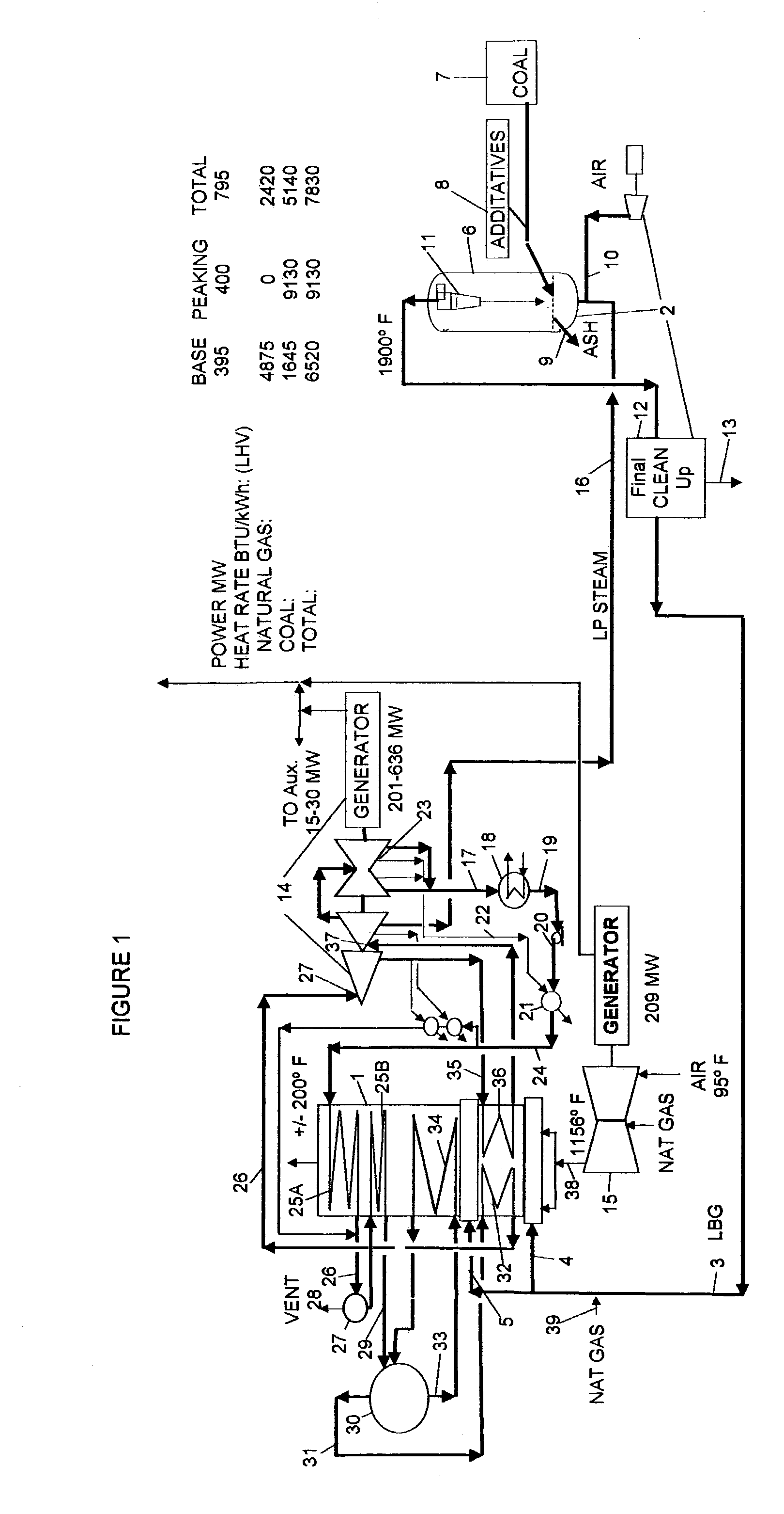
[0024]FIG. 1 is simplified process flow diagram of an embodiment of the combined cycle system of the present invention in a preferred embodiment. Fuel gas is fired in the heat recovery unit 1. The fuel gas is low BTU fuel gas produced in a gasification unit 2. The low BTU gas is injected directly into the gas turbine exhaust gas stream 3 flowing through the heat recovery unit at two points 4, 5. Firing of low BTU gas in the heat recovery unit provides heat in addition to sensible heat transferred from the gas turbine exhaust gas to condensate. The additional heat is used to increase the condensate recycle rate, raising additional steam that generates additional electric power with the steam turbine train 14.

[0025]The gasification reactor 6 is a refractory-lined fluidized bed that operates at between about 20 to 60 psig and about 1800 F to 2200 F. The feed stock for gasification in this example is run of the mine coal 7. The coal is granulated, sized, and conveyed to a lock hopper sy...


PUM


Abstract

A combined cycle process that includes gas turbines, a steam turbine train, a heat recovery unit, and a gasification unit that produces low or mid BTU fuel gas from coal, lignite, coke, biomass, or other suitable hydrocarbon containing material wherein the fuel gas is burned in the heat recovery unit at one or more points to increase steam rate to the steam turbine train.
The fuel gas injection flow rates into the heat recovery unit are controlled to avoid exceeding peak temperatures in the heat recovery unit of about 2500 F.
Optionally, the fuel gas from the gasification unit is cooled by transferring sensible heat to condensate from the steam turbine train to convert the condensate to high pressure steam for driving the steam turbine train.
Optionally, a steam boiler unit is integrated into the combined cycle process to raise additional high pressure steam for the steam turbine train. The steam boiler feed water is condensate from the steam turbine train. The steam boiler produces saturated high pressure steam that is superheated in the heat recovery unit.

Description

FIELD OF THE INVENTION[0001]This invention relates to generation of electric power with combined cycle power plants.BACKGROUND OF THE INVENTION[0002]Combined cycle systems are comprised of:[0003]1) One or more gas turbines each driving an electric power generator;[0004]2) A steam turbine train comprised of steam driven turning a common drive shaft that drives an electric power generator; and[0005]3) A heat recovery unit in which heat in the combined gas turbine combustion exhaust gas stream is transferred to the steam turbine condensate to raise steam for the steam turbine train.[0006]Optionally, a conventional steam boiler unit can be included in the complex to produce additional high pressure steam to increase power output from the steam turbine train. The condensate recycle system for the steam boiler and the heat recovery unit are integrated.[0007]Modern combined cycle units fire fuel gas in the heat recovery unit to supplement the sensible heat transferred from the gas turbine ...

Claims


Application Information

Patent Timeline
Patent Type & Authority Patents(United States)
IPC IPC(8): F01K23/06F02C6/18
CPCF01K23/067F02C6/18Y02E20/18Y02E50/11F05D2220/60F05D2220/72Y02E20/16Y02E50/10
Inventor WYLIE, ROGER
Owner WYLIE INVENTIONS
Why Eureka
Try Eureka