
Method, apparatus and program product for automatic placement and routing of integrated circuit

Inactive Publication Date: 2005-11-22
SOCIONEXT INC
View PDF30 Cites 6 Cited by
  • Summary
  • Abstract
  • Description
  • Claims
  • Application Information

AI Technical Summary

Benefits of technology

[0024]Accordingly, it is an object of the present invention to provide a method, apparatus, and program product for an automatic cell placement and wire routing between cells which can reduce a time needed to cope with crosstalk errors so as to allow reduction in turn around time of development.
[0025]Another object of the present invention is to provide a method, apparatus, and program product for an automatic cell placement and wire routing between cells which can reduce a time needed to cope with self-wire length errors so as to allow reduction in turn around time of development.

Problems solved by technology

Coupling capacitance and coupling inductance between signal lines cause mutual interference (crosstalk), with a result that the signal waveforms are deformed to generate false signals.
However, for example, if one of the lines in parallel is moved in order to resolve the crosstalk error, a new crosstalk may occur between the moved line and its neighboring one, and therefore, the processes of steps S9 to S14 of FIG. 10 are repeated several times in general, causing a problem of increasing turn around time of development (turn around time).
This leads to occurrence of useless regions, tending to increase in chip size more than necessary.
Similarly, such problems occur also in connection with a self-wire length error.

Method used


Image

  • Method, apparatus and program product for automatic placement and routing of integrated circuit
  • Method, apparatus and program product for automatic placement and routing of integrated circuit
  • Method, apparatus and program product for automatic placement and routing of integrated circuit

Examples


Embodiment Construction

[0051]Referring now to the drawings, wherein like reference characters designate like or corresponding parts throughout several views, a preferred embodiment of the present invention is described below.

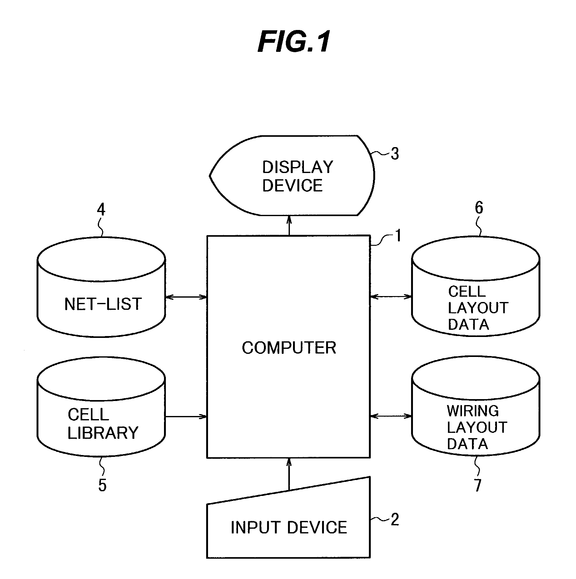
[0052]FIG. 1 is a schematic block diagram showing a hardware construction of an automatic cell placement and wire routing between cells apparatus according to one embodiment of the present invention.

[0053]This apparatus includes a computer 1, and an input device 2, a display device 3, and an external storage device that are coupled to the computer 1. A net-list 4 and a cell library 5 have been stored in this external storage device.

[0054]the computer 1 performs, according to a program installed therein, an automatic placement for cells with using data of the net-list 4 and the cell library 5, and stores its cell layout data 6 in the external storage device; and

[0055](1) performs an error check, described later, in connection with wiring as a preparation before the automatic routing, a...


PUM


Abstract

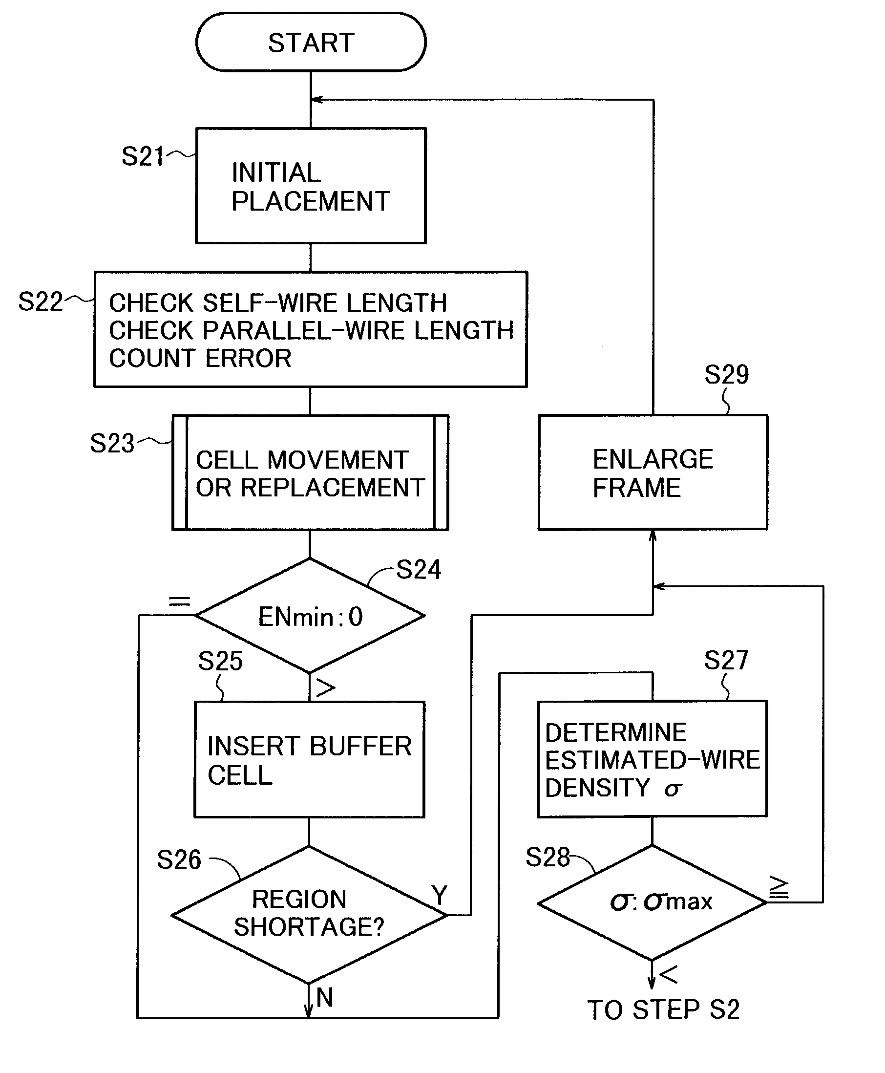
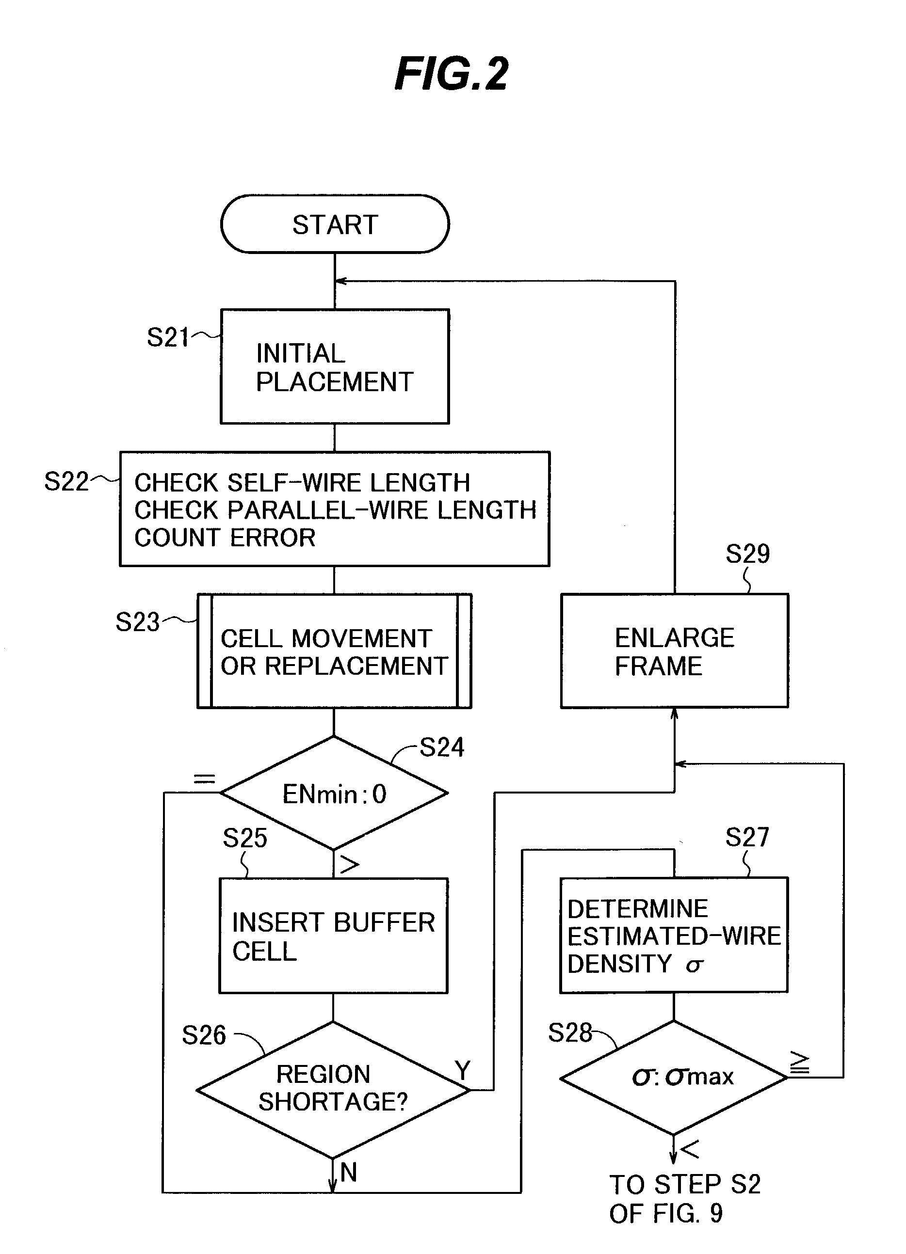
After automatic cell placement, the following steps are performed before performing automatic inter-cell routing. (S22) Estimated wires having Manhattan-length path are connected between same-node terminals of cells, and detected and counted is a crosstalk error that parallel-wire length is more than a predetermined value. (S23) The detected error is resolved by moving cells closely spaced less than a predetermined interval apart and connected to the error-detected estimated wires; the cell movement data is stored in a storage device; and such processes are repeated N times; and the cell placement data is modified on the basis of the cell movement data corresponding to the minimum value of error-count values of all the N times. (S24) If the minimum value is not 0, (S25) a buffer cell is inserted in the error-detected estimated wire. (S27) Obtained is the wire density of estimated wiring having Manhattan-length path, and if the density is more than a predetermined value, the design-target frame is enlarged in size, and the process returns to the automatic cell placement process.

Description

CROSS-REFERENCE TO RELATED APPLICATIONS[0001]This application is based upon and claims the benefit of priority from the prior Japanese Patent Application No. 2002-079086, filed on Mar. 20, 2002, the entire contents of which are incorporated herein by reference.BACKGROUND OF THE INVENTION[0002]1. Field of the Invention[0003]The present invention relates to a method, apparatus, and program product for an automatic cell placement and wire routing between cells in designing the layout of integrated circuit.[0004]2. Description of the Related Art[0005]Coupling capacitance and coupling inductance between signal lines cause mutual interference (crosstalk), with a result that the signal waveforms are deformed to generate false signals. Miniaturization in elements of LSI makes easier the occurrence of crosstalk and leads to increase in time to correct a layout in an automatic cell placement and wire routing between cells.[0006]FIGS. 9 and 10 are flowcharts showing a prior art an automatic ce...

Claims


Application Information

Patent Timeline
IPC IPC(8): G06F17/50H01L21/82
CPCG06F17/5072G06F30/392
Inventor USHIYAMA, KENICHIICHINOSE, SHIGENORIBANNO, KOUJI
Owner SOCIONEXT INC
Learn More