
Electroactive polymer actuated medical devices

Active Publication Date: 2005-11-29
BOSTON SCI SCIMED INC
View PDF25 Cites 1054 Cited by
  • Summary
  • Abstract
  • Description
  • Claims
  • Application Information

AI Technical Summary

Benefits of technology

[0028]One advantage of this second aspect of the present invention is that an apparatus is provided that can be used to make an anastomotic connection, without the need for a high degree of manual suturing skill.

Problems solved by technology

During each of the above procedures, there is a risk that dislodged emboli will travel into smaller diameter regions of the vasculature, blocking blood vessels and causing ischemic injury.
This problem is especially severe where the emboli are permitted to travel into the coronary arteries and cerebral arteries, and can result in infarction, stroke and even death.
Manual suturing is difficult and time-consuming.
In the case of coronary artery bypass procedures, one source of difficulty for suturing of an anastomosis may be motion of the heart.

Method used


Image

  • Electroactive polymer actuated medical devices
  • Electroactive polymer actuated medical devices
  • Electroactive polymer actuated medical devices

Examples


Embodiment Construction

[0044]According to a first aspect of the present invention, a filter apparatus is provided for use in minimally invasive procedures within a tubular body fluid conduit, such as vascular or other procedures where the practitioner desires to capture material that may be dislodged during the procedure.

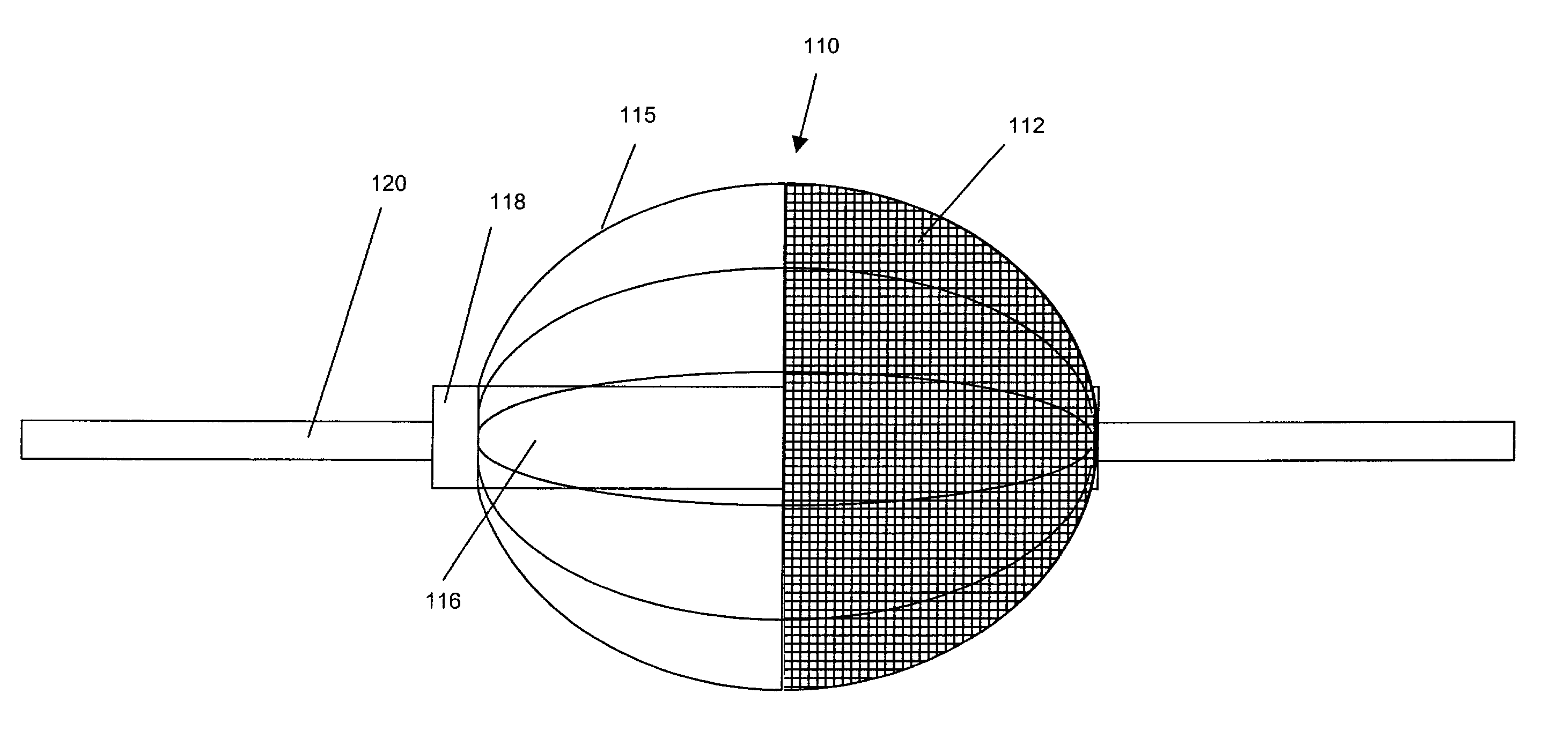
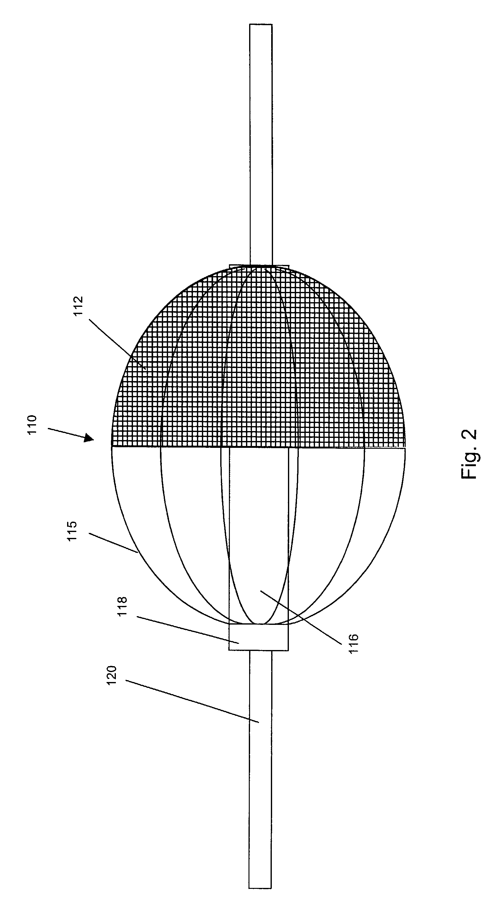
[0045]One specific embodiment of a filter assembly 110 in accordance with the present invention will now be described with reference to FIG. 2. The filter assembly 110 is disposed along guidewire 120. The filter assembly 110 includes a filter element 112, which is typically formed from a suitable mesh or porous material that will filter particulate material (e.g., emboli from blood) while permitting sufficient perfusion therethrough. Such filter elements 112 are well known in the art.

[0046]In the embodiment shown, the filter element 112 is provided with an expandable support frame for outwardly deploying the filter element 112 in a fashion such that it substantially fills the cross sectio...


PUM


Abstract

The present invention is directed to novel apparatus for use in medical procedures relating to tubular body fluid conduits. According to a first aspect of the invention, a filter apparatus is provided for delivery over a guidewire within a tubular body conduit, such as a blood vessel. The filter apparatus comprises: (a) a filter element transformable between a collapsed state and a deployed state, wherein the filter element is adapted to filter particulate matter from fluid within the tubular body conduit while in the deployed state; and (b) a locking member comprising one or more electroactive polymer actuators which switch the locking member between (i) a locking state wherein the locking member securely engages the guidewire and (ii) a release state wherein the locking member is movable along the length of the guidewire. According to a second aspect of the invention, a connector apparatus is provided for use in making an anastomotic connection between first and second tubular fluid conduits in a patient. The connector apparatus comprises: (a) a locking member, which further comprises one or more electroactive polymer actuators that switch the locking member between a locking state and a release state; and (b) a connector body that is configured to permit flow of bodily fluid between the first and second tubular fluid conduits. The connector body has a first portion configured for insertion into an axial end of the first tubular fluid conduit and a second portion configured for insertion through a sidewall of the second tubular fluid conduit. The second portion of the connector body is further configured to securely engage the locking member when the locking member is in the locking state.

Description

FIELD OF THE INVENTION[0001]The present invention relates to devices for use in medical procedures, and more particularly to electroactive-polymer-containing devices for use in medical procedures concerning tubular body fluid conduits.BACKGROUND OF THE INVENTION[0002]Numerous medical procedures are known which involve tubular fluid conduits such as blood vessels. One such procedure, known as percutaneous transluminal angioplasty, involves the use of an angioplasty balloon catheter in a minimally invasive treatment to enlarge a stenotic or diseased blood vessel. In order to prolong the positive effects of percutaneous transluminal angioplasty, a stent may be implanted in conjunction with the procedure to provide radial support to the treated vessel. A thrombectomy is another minimally invasive procedure that may be conducted in lieu of a percutaneous transluminal angioplasty. It is a procedure that can be used to remove an entire thrombosis or a sufficient portion of the thrombosis t...

Claims


Application Information

Patent Timeline
IPC IPC(8): A61B17/064A61B17/11A61F2/01A61F2/06
CPCA61B17/11A61F2/064A61B17/0643A61B2017/1107A61B2017/1135A61F2/013A61M2025/0058Y10S310/80
Inventor ESKURI, ALAN DAVID
Owner BOSTON SCI SCIMED INC
Learn More