Square wave drive system

Inactive Publication Date: 2005-11-29
MICROSEMI
View PDF19 Cites 44 Cited by
  • Summary
  • Abstract
  • Description
  • Claims
  • Application Information

AI Technical Summary

Benefits of technology

[0017]For purposes of summarizing the invention, certain aspects, advantages and novel features of the invention have been described herein. It is to be understood that not necessarily all such advantages may be achieved in accordance with any particular e

Problems solved by technology

Fluorescent lamps are used in a number of applications where light is required but the power required to generate the light is limited.
One problem with a sinusoidal wavef

Method used


Image

  • Square wave drive system
  • Square wave drive system
  • Square wave drive system

Examples


Embodiment Construction

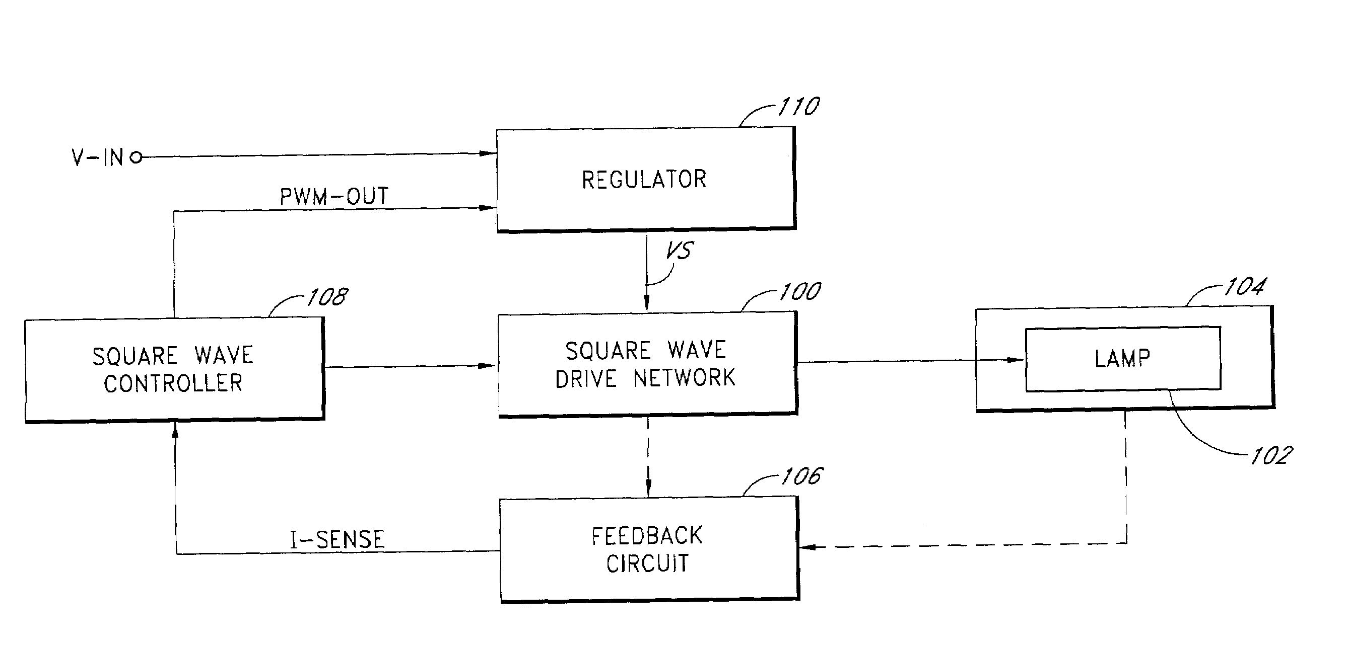
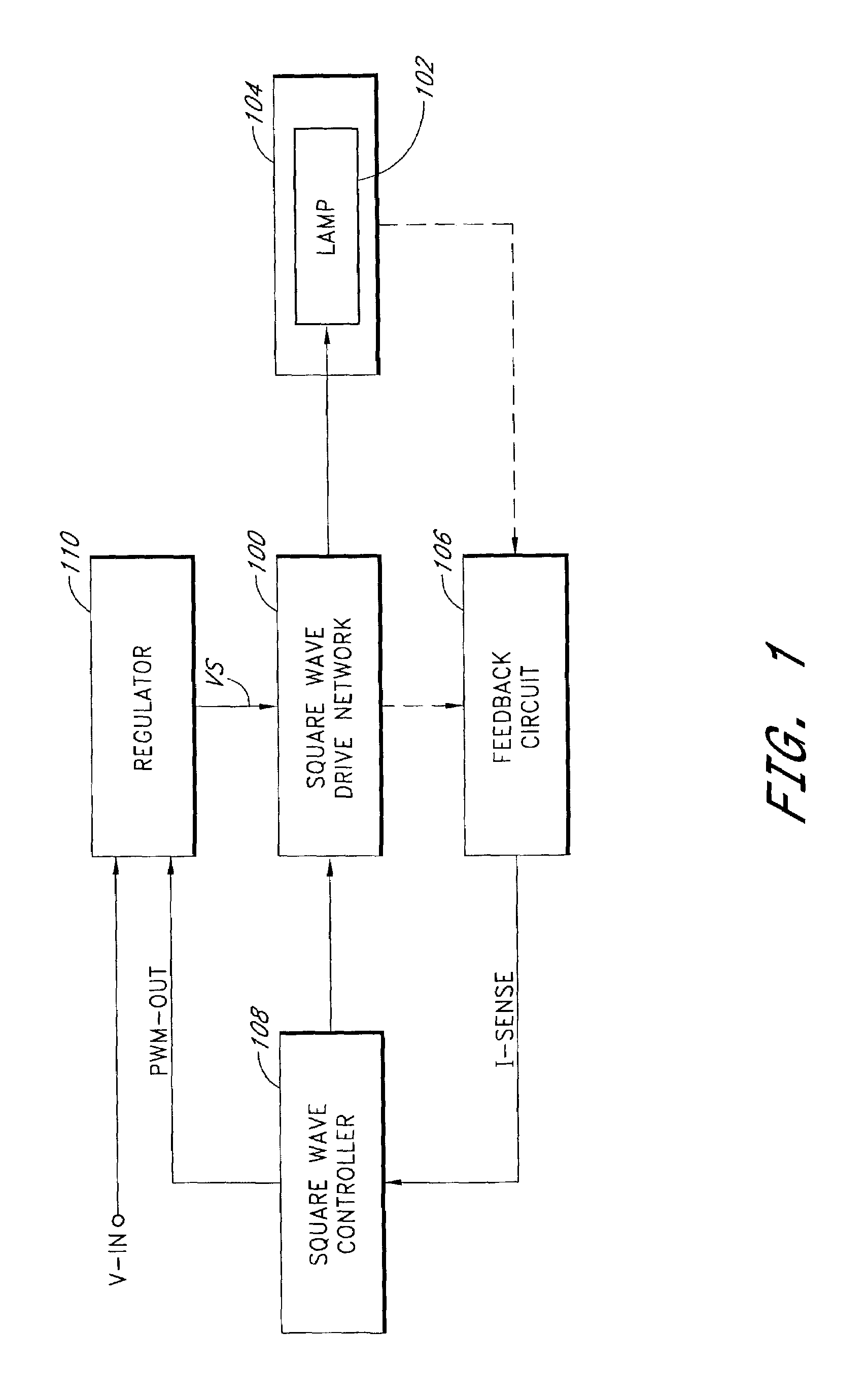
[0027]Embodiments of the present invention will be described hereinafter with reference to the drawings. FIG. 1 is a block diagram of a power conversion circuit (or a lamp inverter) according to one embodiment of the present invention. The power conversion circuit converts a substantially DC input voltage (V-IN) into a substantially square wave output voltage to drive a fluorescent lamp (e.g., a cold cathode fluorescent lamp (CCFL) or a hot cathode fluorescent lamp (HCFL)) 102. A lamp current flows through the fluorescent lamp 102 to provide illumination in an electronic device 104, such as, for example, a flat panel display, a notebook computer, a personal digital assistant, a hand held computer, a liquid crystal display television, a scanner, a facsimile machine, a copier, or the like.

[0028]The power conversion circuit includes a regulator 110, a square wave controller 108, a square wave drive network 100, and a feedback circuit 106. The regulator (or the input stage voltage regul...


PUM


Abstract

A power conversion circuit improves lamp operating life and lamp efficiency by driving a fluorescent lamp with a square wave signal. The square wave signal is an alternating current signal with relatively fast transition times. The square wave signal advantageously reduces lamp current crest factor for more efficient operation of the fluorescent lamp.

Description

CLAIM FOR PRIORITY[0001]This application claims the benefit of priority under 35 U.S.C. § 119(e) of U.S. Provisional Application No. 60 / 389,618 entitled “Lamp Inverter with Pre-Regulator,” filed on Jun. 18, 2002, and U.S. Provisional Application No. 60 / 392,333 entitled “Square Wave Drive System,” filed on Jun. 27, 2002, the entirety of which are incorporated herein by reference.RELATED APPLICATION[0002]Applicant's copending U.S. Patent Application entitled “Lamp Inverter with Pre-Regulator,” filed on the same day as this application, is hereby incorporated by reference herein.BACKGROUND OF THE INVENTION[0003]1. Field of the Invention[0004]The present invention relates to a power conversion circuit for driving fluorescent lamps, such as, for example, cold cathode fluorescent lamps or hot cathode fluorescent lamps, and more particularly relates to a lamp inverter using square wave signals for more efficient operation.[0005]2. Description of the Related Art[0006]Fluorescent lamps are u...

Claims


Application Information

Patent Timeline
IPC IPC(8): H05B41/282H05B41/392
CPCH05B41/2828H05B41/3927Y10S315/07Y10S315/02
Inventor HENRY, GEORGE C.
Owner MICROSEMI
Why Eureka
Try Eureka