Tunable organic VCSEL system

a laser cavity and organic technology, applied in semiconductor lasers, active medium materials, instruments, etc., can solve the problems of increased device life, low carrier mobilities of devices, and low optical and thermal damage thresholds of organic materials

Inactive Publication Date: 2005-11-29
EASTMAN KODAK CO
View PDF19 Cites 13 Cited by
  • Summary
  • Abstract
  • Description
  • Claims
  • Application Information

AI Technical Summary

Benefits of technology

[0017]The present invention is directed to meeting one or more of the needs set forth above. Briefly summarized, according to one embodiment of the present invention, we describe a system for mechanically tuning optical wavelengths emitted from an organic laser cavity device, that includes: a multi-layered film structure, wherein the multi-layered film structure is pumped by an incoherent source of photons; and a micro-electromechanical mirror assembly proximate to the multi-layered film structure, wherein the micro-electromechanical mirror assembly varies the cavity length of the organic laser cavity device.
[0018]According to another embodiment of the present invention, directed to meet one or more of the aforementioned needs, we describe a system for tuning optical wavelengths emitted from an organic laser cavity device, that includ

Problems solved by technology

A problem with all of these structures is that in order to achieve lasing it was necessary to excite the cavities by optical pumping using another laser source.
This low carrier mobility results in a number of problems.
Devices with low carrier mobilities are typically restricted to using thin layers in order to avoid large voltage drops and ohmic heating.
Organic materials can suffer from low optical and thermal damage thresholds.
Efforts to reduce sensitivity to these variables typically result in increased device lifetime.
These alternative means a

Method used


Image

  • Tunable organic VCSEL system
  • Tunable organic VCSEL system
  • Tunable organic VCSEL system

Examples


second embodiment

[0076]In a second embodiment, the dielectric control layer 1020 comprises a photorefractive material. Lithium niobate doped with Fe+3 is a candidate material. In this case, the controller 1040 is an optical source, such as a UV lamp, and the refractive index changes in response to the intensity.

third embodiment

[0077]As a third embodiment, the dielectric control layer 1020 comprises a material that is thermally sensitive, and the controller 1040 is a thermal source, such as a resistive heating element. The dielectric control layer can then modify the laser wavelength via thermal expansion and / or by thermally induced changes to the refractive index, i.e. Lopt⁡(Δ⁢ ⁢T)=Lopt,0+nd⁢ ⁢c,o⁢∂Ld⁢ ⁢c∂T+Ld⁢ ⁢c,o⁢∂nd⁢ ⁢c∂T,

where ΔT is the variation of the temperature from a steady-state temperature, Lopt,o is the optical cavity length at the steady-state temperature, ndc is the refractive index of the dielectric control layer, and Ldc is the physical thickness of the dielectric control layer.

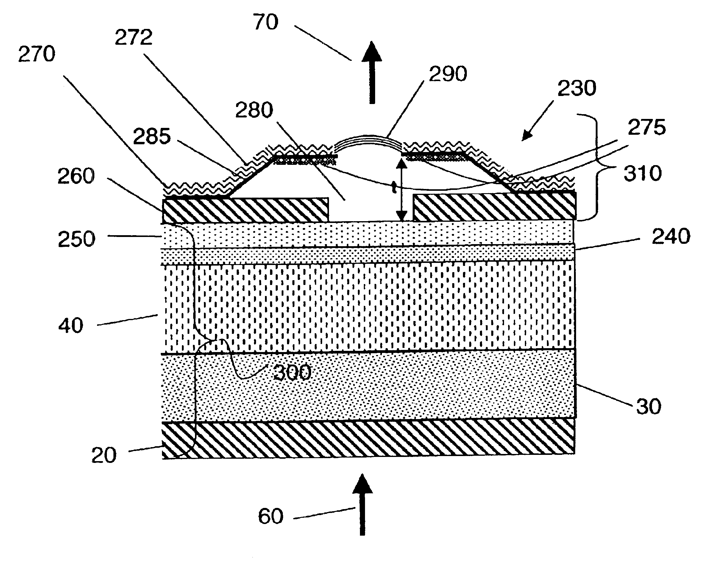
[0078]In FIG. 18 a MEMs device is included for changing the optical path length of the laser cavity. The MEMs device is placed atop index matching layer or layers 240 and 250. The micro-electromechanical mirror assembly 310 consists of a bottom electrode 260, a support structure 270, a top electrode 275, support ar...


PUM


Abstract

A system for mechanically tuning optical wavelengths emitted from an organic laser cavity device, that includes: a multi-layered film structure, wherein the multi-layered film structure is pumped by an incoherent source of photons; and a micro-electromechanical mirror assembly proximate to the multi-layered film structure, wherein the micro-electromechanical mirror assembly varies the cavity length of the organic laser cavity device.

Description

CROSS-REFERENCE TO RELATED APPLICATIONS[0001]Reference is made to commonly assigned U.S. patent application Ser. No. 09 / 832,759 filed Apr. 11, 2001 titled “Incoherent Light-Emitting Device Apparatus for Driving Vertical Laser Cavity” by Keith B. Kahen et al.; commonly assigned U.S. patent application Ser. No. 10 / 066,936 filed Feb. 4, 2002 titled “Organic Vertical Cavity Lasing Devices Containing Periodic Gain Regions” by Keith B. Kahen et al.; and commonly assigned U.S. patent application Ser. No. 10 / 066,829 filed Feb. 4, 2002 titled “Organic Vertical Cavity Phase-Locked Laser Array Device” by Keith B. Kahen, the disclosures of which are incorporated herein by reference.FIELD OF THE INVENTION[0002]The invention relates generally to the field of Vertical Cavity Surface Emitting Lasers (VCSEL) or microcavity lasers, and in particular to organic microcavity lasers or organic VCSELs. More specifically, the invention relates to the wavelength tuning of organic laser cavities.BACKGROUND O...

Claims


Application Information

Patent Timeline
IPC IPC(8): G02B5/28H01S3/05G02B5/26H01S3/0933H01S3/10H01S3/105H01S3/107H01S3/17H01S5/04H01S5/06H01S5/14H01S5/183H01S5/30H01S5/36
CPCH01S5/18366G02B26/001H01S3/0933H01S3/168H01S5/041H01S5/141H01S5/18383H01S5/36
Inventor SPOONHOWER, JOHN P.AGOSTINELLI, JOHN A.KRUSCHWITZ, BRIAN E.KAHEN, KEITH B.LEBENS, JOHN A.
Owner EASTMAN KODAK CO
Why Eureka
Try Eureka