Emergency supply system to supplant interrupted public and private utilities

a supply system and emergency technology, applied in the field of emergency systems, can solve the problems of high cost, inability to heat an entire house in freezing weather with electrical resistance heating, and inability to meet the needs of emergency situations,

Inactive Publication Date: 2005-12-06
COWAN LEROY FR
View PDF8 Cites 24 Cited by
  • Summary
  • Abstract
  • Description
  • Claims
  • Application Information

AI Technical Summary

Benefits of technology

[0009]In addition, the back-up system includes at least one water storage reservoir for potable water that is coupled to the water main through an anti-siphon valve. The anti-siphon valve cuts off the connection to the water main when the pressure in the water main drops below a set value, thereby preventing water from the water storage reservoir(s) from being depleted through siphoning. There is also a readily-accessible shut-off valve (in addition to the water utility shut-off valve next to the water meter), with which the supply water from the municipal water supply may be cut if, for example, it is contaminated. With the municipal water supply cut off, water for the building is drawn from the water storage reservoirs. Until the municipal water supply is considered safe, or restored, the water in the water storage reservoirs can be replenished from safe sources. Each water storage reservoir is eq...

Problems solved by technology

In the event of an emergency, such as an earthquake or other catastrophic event, public utility delivery systems for potable water, natural gas, and electric power are likely to be disrupted.
However, if the event were to occur in a time of freezing weather, a lack of natural gas (or an alternative replacement fuel) and/or electric power might conceivably pose a life-threatening situation.
However, due to the cost per term of heat generated via electrical resistance, it may be prohibitively expensive to...

Method used


Image

  • Emergency supply system to supplant interrupted public and private utilities
  • Emergency supply system to supplant interrupted public and private utilities
  • Emergency supply system to supplant interrupted public and private utilities

Examples


Embodiment Construction

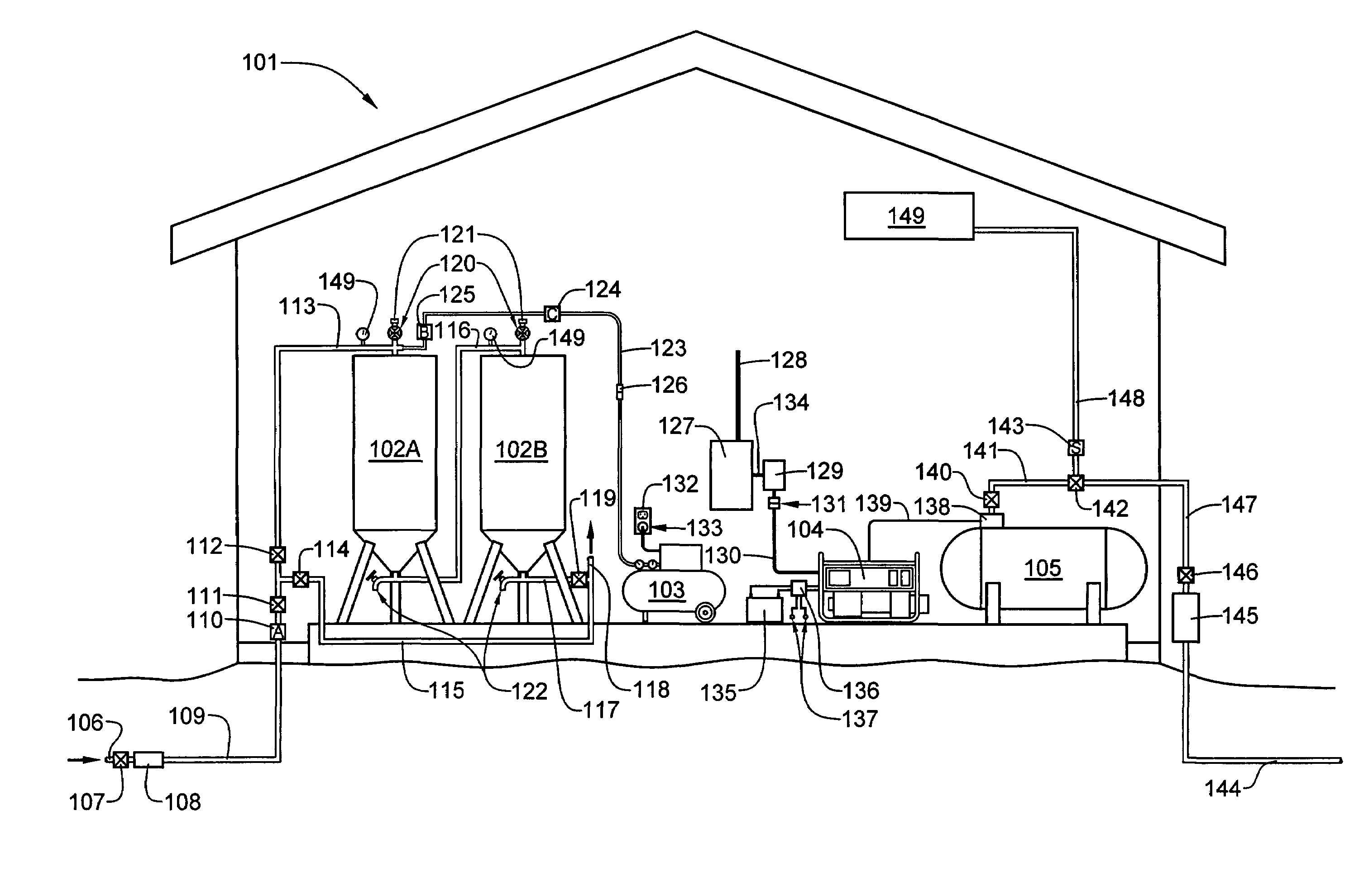
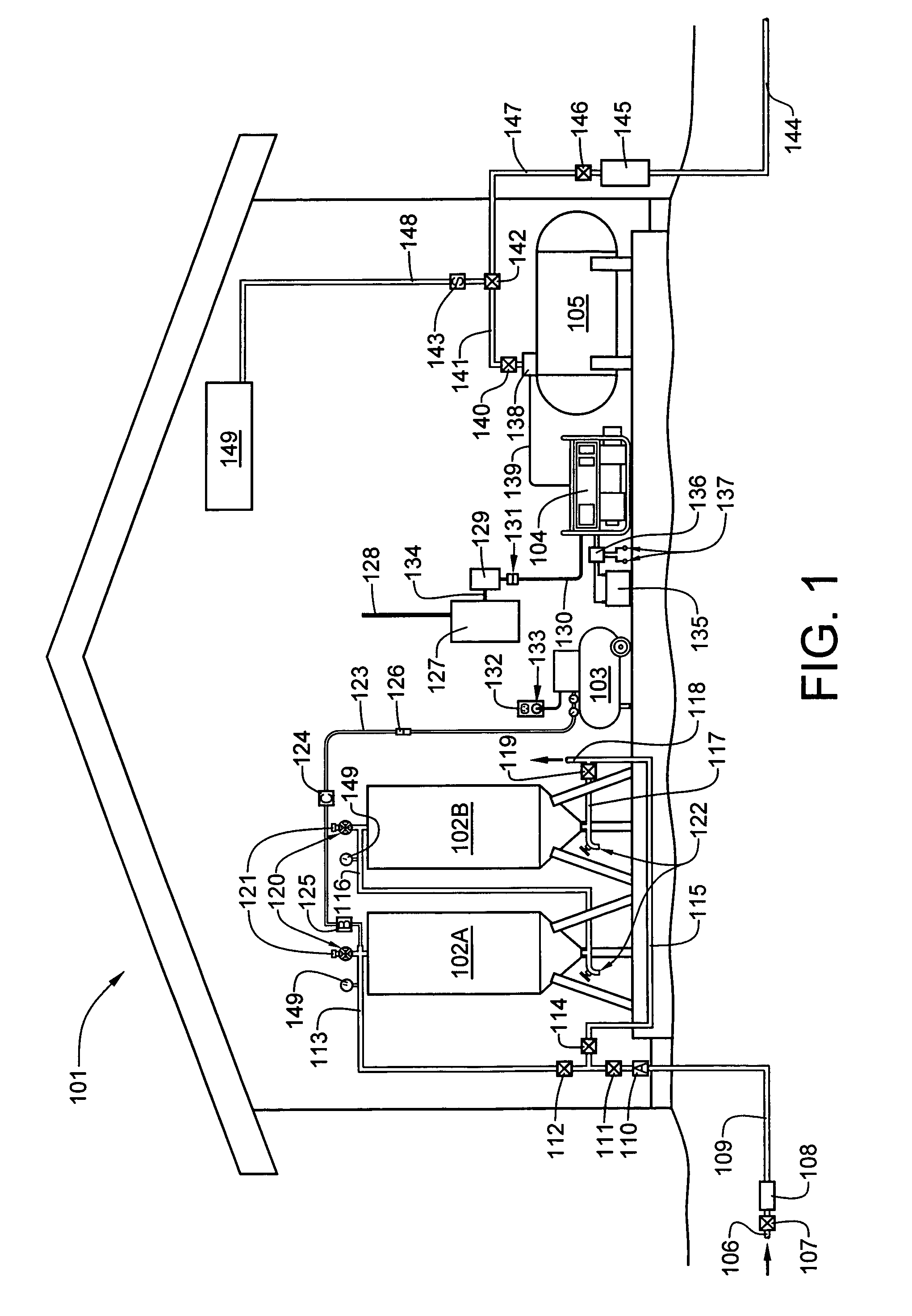
[0013]Referring now to FIG. 1, a preferred embodiment of an integrated emergency back-up system for a building, such as a residence 101, that is normally supplied with culinary water, electric power and natural gas by one or more public utility companies, includes a pair of series connected water storage reservoirs 102A and 102B, an air compressor 103, an electric generator 104, a fuel storage tank 105 for liquid hydrocarbon fuel. The electric generator may be powered by an internal combustion engine, a wind turbine, or any other available source of rotational energy. Alternatively, the electric generator may utilize solar cells or fuel cells.

[0014]As most residential heating systems (furnaces) are fired by natural gas provided by a utility distribution grid, it would be ideal if natural gas could be stored in quantities sufficient to meet emergency demands. However, the major component of natural gas is methane, and long-term storage of liquified methane is impractical, at best, as...


PUM


Abstract

An emergency utility backup system, for a building normally supplied with culinary water, electric power and natural gas by public utilities, includes at least one water storage reservoir having an upper input coupled to a public water utility main line; an electric generator powered by an internal combustion engine; and an electric air compressor having a compressed air storage tank which provides elevated air pressure to the water storage reservoir(s) in the event that water pressure from the public water utility main line fails. The electric air compressor is operable from power supplied by either a public electric utility or said electric generator. The emergency utility backup system may also include a tank for storing a liquid hydrocarbon fuel that may be utilized for both the electric generator and a heating system for the building. Electric power to the building is supplied either from an electric utility source through circuit breakers located within a main circuit breaker panel, of from the electric generator through breakers in a load distribution and transfer switch box.

Description

FIELD OF THE INVENTION[0001]This invention relates, generally, to emergency systems for a supply of water, electric power, and hydrocarbon fuels used for cooking and / or heating. More particularly, the invention relates to such emergency systems having interrelated and shared components.BACKGROUND OF THE INVENTION[0002]Potable water, electric power and natural gas are typically provided to individual subscribers by public utility companies. The term “public utility” denotes that the public receives either the water, power or gas from the companies, but does not imply that those companies are necessarily publically owned, as they may be either publically or privately owned. In the event of an emergency, such as an earthquake or other catastrophic event, public utility delivery systems for potable water, natural gas, and electric power are likely to be disrupted. If such an emergency event were to occur, a lack of potable water would likely be of most immediate concern. However, if the...

Claims


Application Information

Patent Timeline
IPC IPC(8): E03B1/00
CPCE03B1/00Y10T137/3127Y10T137/6969
Inventor COWAN, LEROY FRANK
Owner COWAN LEROY FR
Why Eureka
Try Eureka