Isolated shield coaxial surge suppressor

a coaxial surge and suppressor technology, applied in the direction of overvoltage protection resistors, emergency protective arrangements for limiting excess voltage/current, coupling device connections, etc., can solve the problems of high cost of coils and wide band frequency response, severe damage to electronic equipment, and hum, etc., to achieve uniform impedance characteristics

Inactive Publication Date: 2005-12-13
INFINITE ELECTRONICS INT INC
View PDF30 Cites 32 Cited by
  • Summary
  • Abstract
  • Description
  • Claims
  • Application Information

AI Technical Summary

Benefits of technology

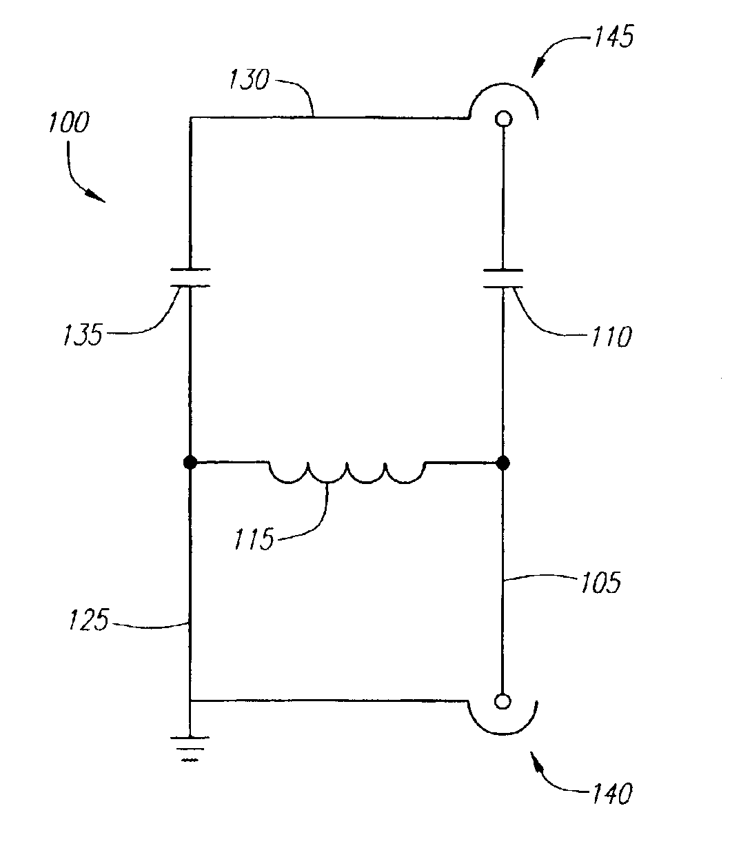
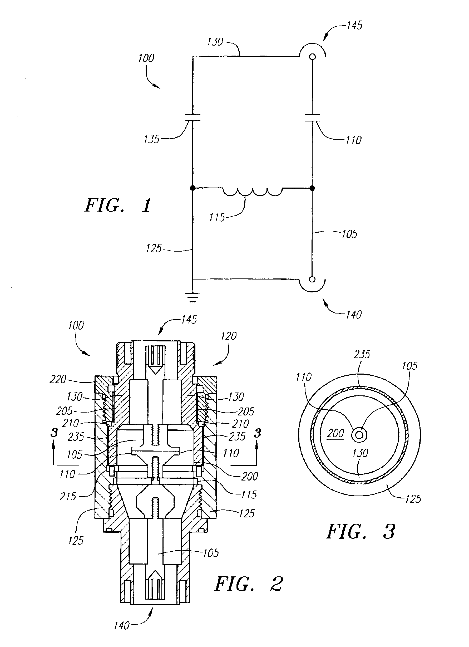
[0009]By way of example, one embodiment of the present invention is a surge suppressor device configured to maintain a uniform impedance characteristic. The surge suppressor device can include a housing having a surge port shield and a protected port shield, the surge port shield being positioned adjacent to the protected port shield, and a conductor, positioned within the housing, having a surge port for receiving an rf signal and a surge and a protected port for propagating the rf signal. The surge suppressor device can also include a surge blocking device coupled in series between the surge port and the protected port, a device, coupled to the surge port, for diverting the surge to the surge port shield, and a shield coupling dielectric positioned between the surge port shield and the protected port shield. This configuration can help to prevent the electrical surge from passing from the surge port to the protected port via the conductor or shields. Furthermore, this configuration can attenuate out of band frequencies from passing through the surge suppressor device while passing desirable in-band rf frequencies. Hence, the present invention provides a means of achieving coaxial surge suppression and electrical isolation between the surge port and the protected port.
[0010]Another embodiment of the present invention is an apparatus comprising a conductor having an input end and an output end, an input shield positioned around at least a portion of the input end of the conductor, and an output shield positioned around at least a portion of the output end of the conductor. The apparatus also might include a capacitor positioned between the input end of the conductor and the output end of the conductor, and a dielectric disposed between the input shield and the output shield for preventing dc current from coupling from the input shield to the output shield.
[0011]Another embodiment of the present invention is a surge protection device comprising a conductor for receiving an rf signal and a dc current, a first shield having a lumen configured to accommodate at least a portion of the conductor, and a second shield having a lumen configured to accommodate the first shield so that a portion of the first shield is positioned within the lumen of the second shield. The surge protection device further comprises a dc blocking device, coupled to the conductor, for attenuating the dc current, a device, coupled to the conductor, for diverting the dc current to the second shield, and a dielectric disposed between the first shield and the second shield for preventing the dc current from traveling from the second shield to the first shield.
[0013]Several advantages of the surge protection device include enhanced coupling of the desirable in-band rf frequencies, reduced amounts of rf leakage, isolation between the surge port and the protected port, preventing the electrical surge from passing from the surge port to the protected port via the conductor or shields and maintaining a uniform impedance characteristic. Additional advantages of the surge protection device include ultra low surge throughput specifications, wider operating frequency range per band types, small footprint area, stacked mechanical assembly, high voltage insulation between the surge port and the isolated or protected port, and mechanical capture of the isolated port.

Problems solved by technology

Large variations in the power and transmission line currents and voltages can change the operating frequency range of the electronic equipment and can severely damage and / or destroy the electronic equipment.
When a signal is transmitted along the transmission lines at various frequencies, such as between about 100 MHz to 6 GHz, and across the surge protection device, interference or distortion caused by the ground loop may alter the signal resulting in what is typically referred to as “hum”.
The interference and distortion may modulate the signal trying to pass the surge protection device and may also corrupt the data encoded in the signal, thus making it unusable.
These types of coils are expensive to manufacture with a wide band frequency response, and invariably produce an attenuation of higher frequencies, due to the long length of the cable contained in the coil.
In either case, there may be some degradation of the signal-to-noise ratio, and the additional circuitry may introduce non-linear distortions that can affect the differential phase or gain, or other characteristics, of the signal path.
Hence, one drawback of conventional surge protection devices is the difficulty in preventing ground loops.
Another drawback of conventional surge protection devices is the interference and distortion, such as hum, caused by ground loops.
Yet another drawback of conventional surge protection devices is the attenuation of higher frequencies and the degradation of the signal-to-noise ratio.

Method used


Image

  • Isolated shield coaxial surge suppressor
  • Isolated shield coaxial surge suppressor

Examples


Embodiment Construction

[0018]Surge protection devices that implement the various features of the present invention will now be described with reference to the drawings. The drawings and the associated descriptions are provided to illustrate embodiments of the present invention and not to limit the scope of the present invention. Reference in the specification to “one embodiment” or “an embodiment” is intended to indicate that a particular feature, structure, or characteristic described in connection with the embodiment is included in at least an embodiment of the invention. The appearances of the phrase “in one embodiment” in various places in the specification are not necessarily all referring to the same embodiment. Throughout the drawings, reference numbers are re-used to indicate correspondence between referenced elements. In addition, the first digit of each reference number indicates the figure in which the element first appears.

[0019]Referring now more particularly to the drawings, FIG. 1 is a sche...


PUM


Abstract

A surge protection device is disclosed that includes a conductor for receiving an rf signal and a dc current, a first shield having a lumen configured to accommodate at least a portion of the conductor, and a second shield having a lumen configured to accommodate the first shield so that a portion of the first shield is positioned within the lumen of the second shield. The surge protection device further includes a dc blocking device, coupled to the conductor, for attenuating the dc current, a device, coupled to the conductor, for diverting the dc current to the second shield, and a dielectric disposed between the first shield and the second shield for preventing the dc current from traveling from the second shield to the first shield.

Description

CROSS-REFERENCE TO RELATED APPLICATION[0001]This application relates to and claims priority from U.S. Provisional Patent Application Ser. No. 60 / 367,000, filed Mar. 21, 2002, entitled “METHOD AND APPARATUS FOR MAINTAINING A UNIFORM IMPEDANCE CHARACTERISTIC IN A SURGE SUPPRESSOR DEVICE,” which is herein incorporated by reference for all purposes.BACKGROUND OF THE INVENTION[0002]1. Field of the Invention[0003]The present invention relates generally to the field of surge protection, and more particularly to an isolated shield coaxial surge suppressor.[0004]2. Description of the Related Art[0005]Surge protection devices protect electronic equipment from being damaged by large variations in the current and voltage across power and transmission lines resulting from lightning strikes, switching surges, transients, noise, incorrect connections, and other abnormal conditions or malfunctions. Large variations in the power and transmission line currents and voltages can change the operating fr...

Claims


Application Information

Patent Timeline
Patent Type & Authority Patents(United States)
IPC IPC(8): H01R13/646H01R13/66H02H9/00
CPCH01R24/48H02H9/001H01R13/6666H01R2103/00
Inventor JONES, JONATHAN L.DUNNING, RICHARD C.MATTSON, MARK J.
Owner INFINITE ELECTRONICS INT INC
Why Eureka
Try Eureka