Integrated Fischer-Tropsch and power production plant with low CO2 emissions

a technology of integrated fischertropsch and power production plant, which is applied in the direction of combustible gas production, combustible gas purification/modification, machines/engines, etc., can solve the problem that the syngas produced can be contaminated with unwanted impurities

Inactive Publication Date: 2005-12-20
RES USA LLC
View PDF49 Cites 81 Cited by
  • Summary
  • Abstract
  • Description
  • Claims
  • Application Information

AI Technical Summary

Problems solved by technology

The syngas produced can be contaminated with unwanted impurities such as chlorine and other toxic materials which must be safely removed and stored.

Method used


Image

  • Integrated Fischer-Tropsch and power production plant with low CO2 emissions
  • Integrated Fischer-Tropsch and power production plant with low CO2 emissions

Examples


example 1

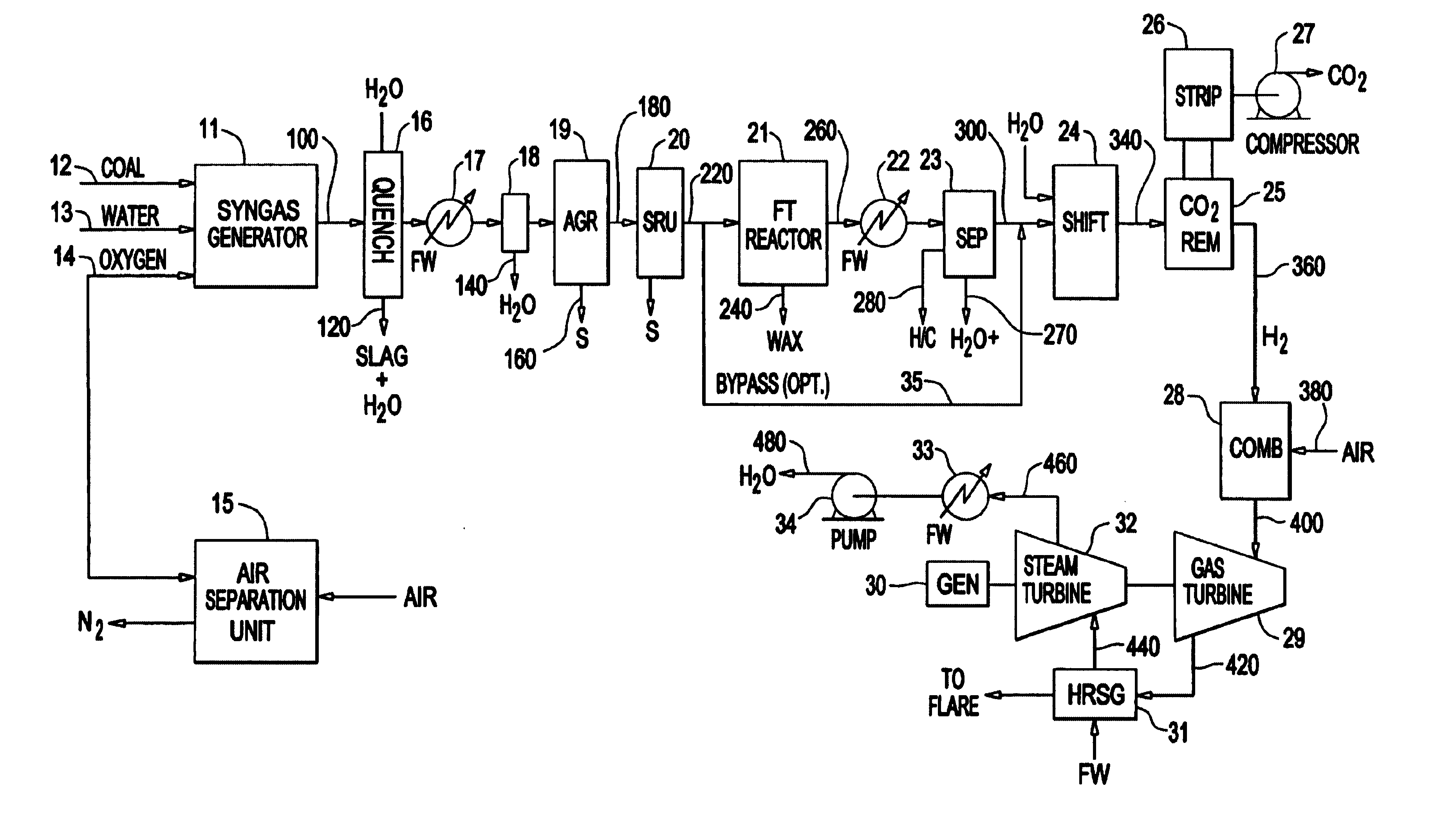
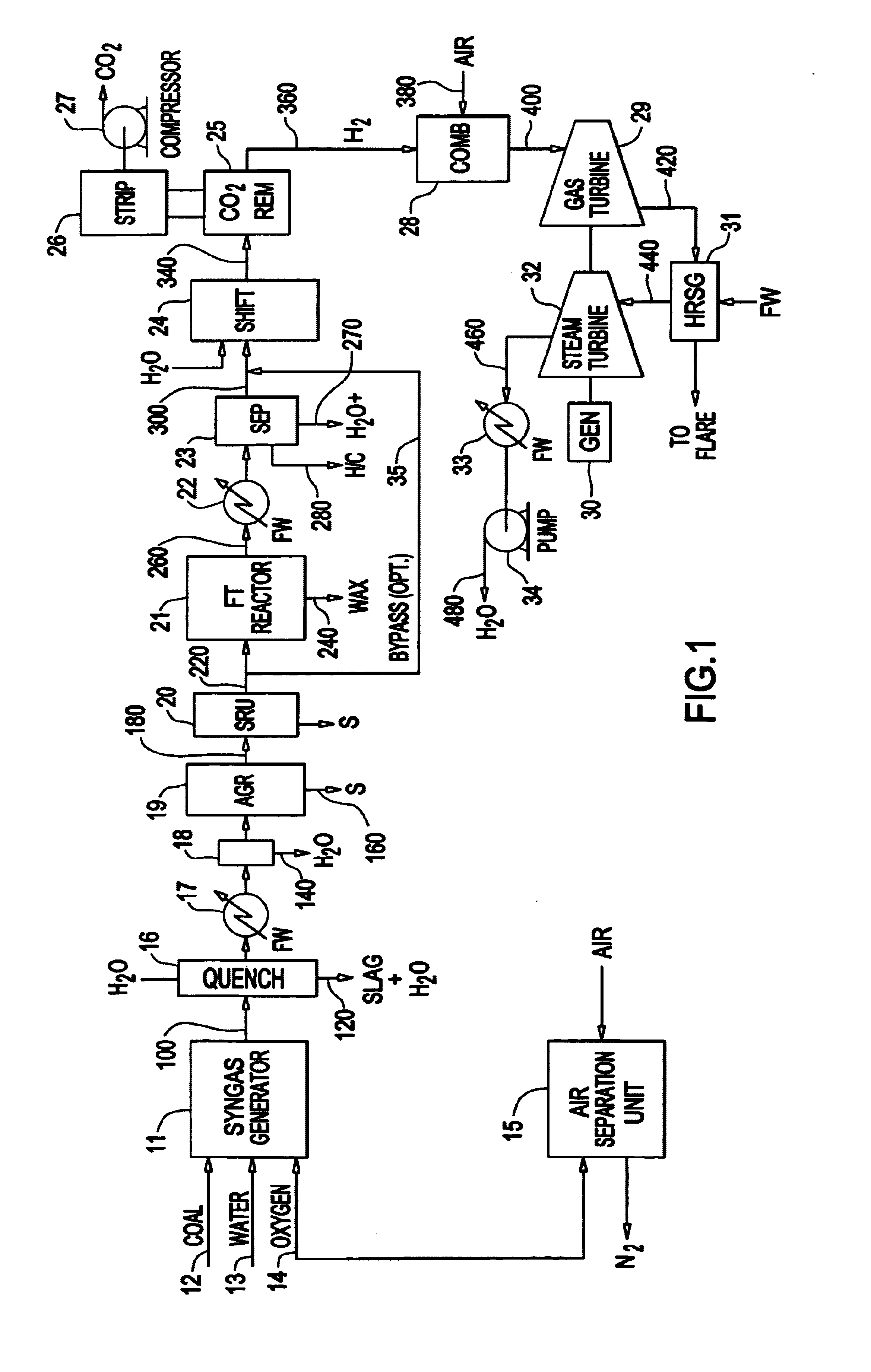
Coal Gasification to FT Liquids, Electrical Power and CO2

[0018]Example 1 is a computer simulation based on the flow sheet of FIG. 1.

[0019]5500 tpd Pittsburgh #8 coal is gasified with 3091 tpd water and 4806 tpd oxygen. The coal is 74.16% by weight carbon. After quenching and cleaning, 47.2% of the syngas is sent to a FT reactor using an iron-based catalyst to produce 6000 barrels per day of C5+ hydrocarbon products and tail gases. After separating the FT hydrocarbon products from the FT tail gases, the tail gases and the other 52.8% of the syngas are mixed with 233 MMSCFD of steam and sent to a low-temperature shift reactor. The gases leaving the shift reactor having achieved equilibrium conditions at 250° C. are comprised on a volume basis of approximately 38.0% H2, 37.5% CO2, 23.0% H2O, and less than 1% of CO, CH4 and N2. After removing 11,300 tpd of CO2 for sequestration and condensing the water from the tail gases, the remaining stream of predominantly H2 is used as fuel in the...


PUM

PropertyMeasurementUnit
temperatureaaaaaaaaaa
weight ratioaaaaaaaaaa

Abstract

A plant for producing Fischer-Tropsch liquids and electrical power with greatly reduced emissions of carbon dioxide to the atmosphere is made up of a syngas generator unit, an air separation unit, a Fischer-Tropsch unit, a CO2 removal unit, and a combined cycle electricity generation unit. Each of Fischer-Tropsch liquids, carbon dioxide, and electrical power can be recoverable under proper economic conditions. Electrical power is recoverable by the use of a gas turbine fueled by predominantly hydrogen and a steam turbine powered by steam generated by cooling exhaust gases from the gas turbine. Sequestration of CO2 and fueling the gas turbine with hydrogen reduces the amount of greenhouse gases emitted to the atmosphere.

Description

CROSS REFERENCE TO RELATED APPLICATION[0001]This is a continuation-in-part of U.S. Patent Application Ser. No. 09 / 963,349 filed Sep. 25, 2001, titled “Integrated UREA Manufacturing Plants and Processes” which issued as U.S. Pat. No. 6,632,846 on Oct. 14, 2003.FIELD OF THE INVENTION[0002]Syngas generators, such as reformers and gasifiers of hydrocarbon fluids and solid carbonaceous materials, and Fischer Tropsch (FT) units, primarily for creating liquid hydrocarbons from syngas, are combined to create an integrated plant for providing one or more of urea, ammonia, carbon dioxide, electric power, and even sulfur when dealing with sulfur-containing raw material.BACKGROUND OF THE INVENTION[0003]Our modern civilization cannot be sustained without burning carbonaceous materials for primarily motive and electrical power within the foreseeable future. The carbon dioxide (CO2) generated by such burning may be contributing to the gradual increase of the planet's temperature since 1900. This i...

Claims


Application Information

Patent Timeline
Patent Type & Authority Patents(United States)
IPC IPC(8): C01B3/32C10G2/00C10J3/00C10J3/86F01K23/06F02C3/22
CPCC01B3/32C10G2/32C10G2/332C10J3/00C10J3/86C10K1/004C10K1/005C10K1/101C10K1/143F01K23/06F01K23/068F02C3/22F25J3/04539C01B2203/0283C01B2203/062C01B2203/86C10J2300/093C10J2300/0959C10J2300/0973C10J2300/165C10J2300/1659C10J2300/1675C10J2300/1678F25J2260/80Y02E20/185Y02E20/16Y02E20/18Y02E20/32Y02P20/151Y02P30/00
Inventor SHEPPARD, RICHARD O.YAKOBSON, DENNIS L.
Owner RES USA LLC
Why Eureka
Try Eureka