Radiological imaging apparatus and radiological imaging method

a radiological imaging and apparatus technology, applied in tomography, instruments, nuclear engineering, etc., can solve the problems of complex apparatus configuration of radiological imaging apparatuses, inability to obtain the angle of incidence upon the detector, and inability to identify the detailed position of the focus, etc., to achieve the effect of simplifying the configuration of radiological imaging apparatus

Inactive Publication Date: 2005-12-20
HITACHI LTD
View PDF21 Cites 43 Cited by
  • Summary
  • Abstract
  • Description
  • Claims
  • Application Information

AI Technical Summary

Benefits of technology

[0009]It is an object of the present invention to provide a radiological imaging apparatus and radiological imaging method in a simplified apparatus configuration.

Problems solved by technology

In the case of the SPECT, single γ-rays are radiated, and therefore it is not possible to obtain their angle of incidence upon the detector.
However, because of the absence of information on the correspondence with the physical locations of an examinee, the detailed position of the focus may remain unidentified.
Furthermore, equipped with two image pickup apparatuses each provided with a radiation detector, etc., these radiological imaging apparatuses have a complicated apparatus configuration.

Method used


Image

  • Radiological imaging apparatus and radiological imaging method
  • Radiological imaging apparatus and radiological imaging method
  • Radiological imaging apparatus and radiological imaging method

Examples


embodiment 1

(Embodiment 1)

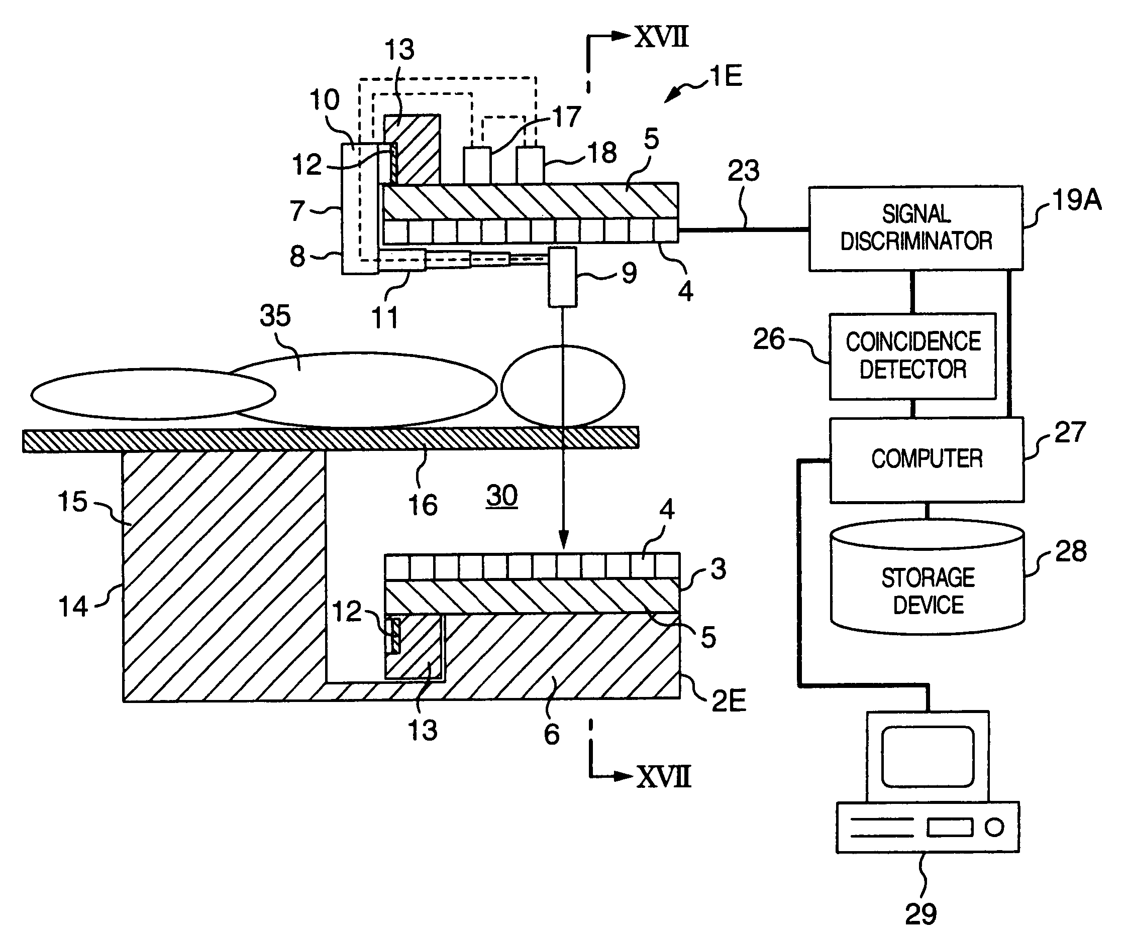
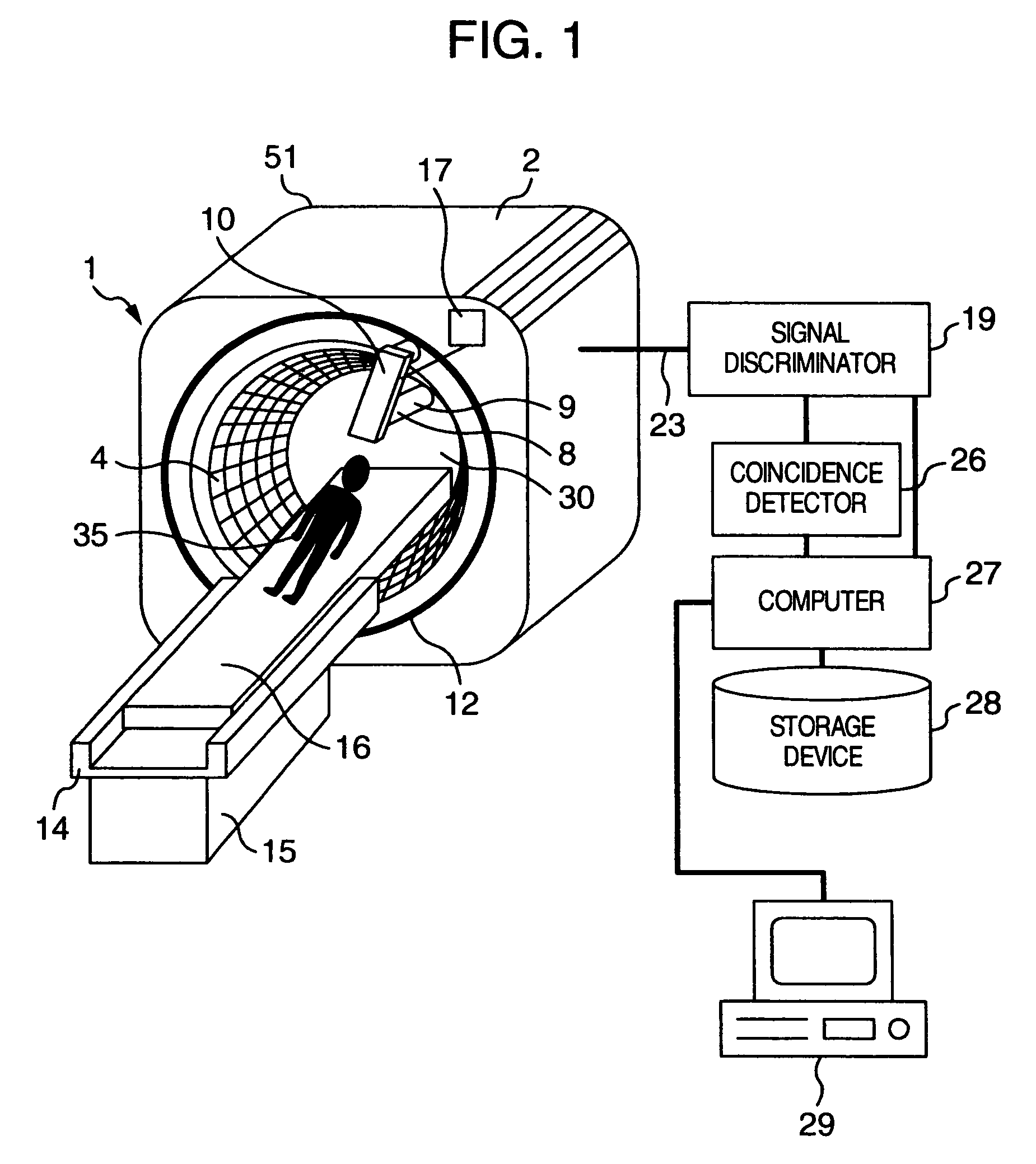
[0040]With reference now to FIG. 1 and FIG. 2, a radiological imaging apparatus which is a preferred embodiment of the present invention will be explained below. A radiological imaging apparatus 1 of this embodiment is provided with an image pickup apparatus 2, an examinee holding apparatus 14, a signal discriminator 19, a coincidence detector 26, a storage device 28, a computer 27 and a display device 29. The examinee holding apparatus 14 includes a support 15 and a bed installed on top of the support 15 in a manner movable in a longitudinal direction. The image pickup apparatus 2 includes radiation detectors 4, a casing 15 provided with a through hole section 30, an X-ray source apparatus 8, a guide rail 12 and a drive controller 17. The image pickup apparatus 2 is installed in a direction perpendicular to the longitudinal direction of the bed 16. The radiation detector 4 is a semiconductor radiation detector. Many radiation detectors 4 (10000 in total) are set in th...

embodiment 2

(Embodiment 2)

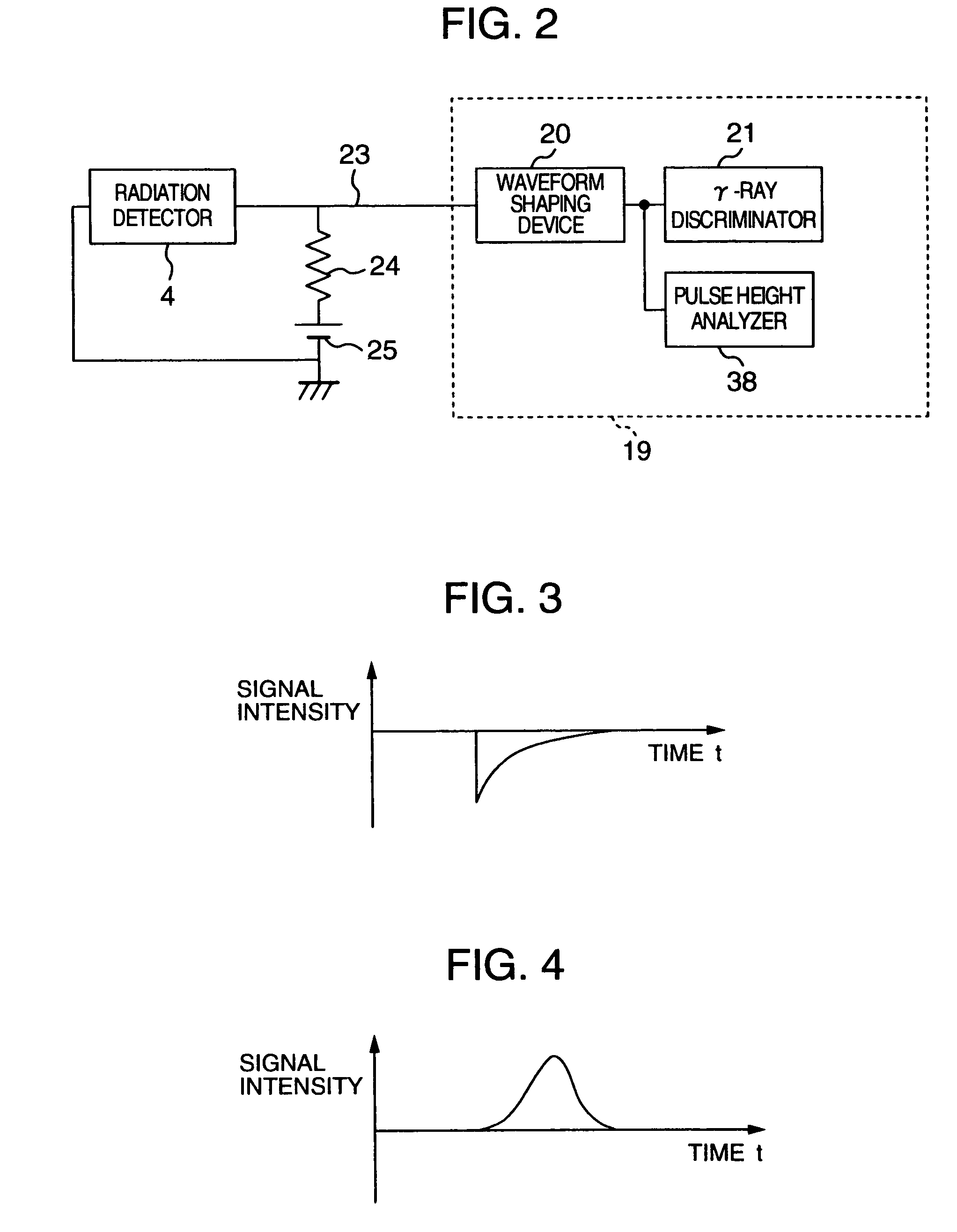
[0070]A radiological imaging apparatus according to another embodiment of the present invention will be explained. Though not shown, the configuration of this embodiment uses a signal discriminator 19A shown in FIG. 8 instead of the signal discriminator 19 in the configuration in FIG. 1. The signal discriminator 19A can also be used as a substitute for the signal discriminator 19 in Embodiment 4, which will be described later. The signal discriminator 19A has a configuration with a changeover switch 31 added to the aforementioned signal discriminator 19 and the pulse height analyzer 38 replaced by a signal processor 22. The signal discriminator 19A is provided with a waveform shaping device 20, a γ-ray discriminator 21 and the signal processor 22 for calculating the intensity of X-rays. The signal processor 22 is provided with an integrator (not shown). The changeover switch 31 includes a movable terminal 32 and fixed terminals 33 and 34. Wiring 23 is connected to the ...

embodiment 3

(Embodiment 3)

[0079]A radiological imaging apparatus according to another embodiment of the present invention will be explained using FIG. 10. This embodiment shows an example of conducting X-ray computed tomographic inspection and PET inspection using one image pickup apparatus 2A. The radiological imaging apparatus 1A of this embodiment is provided with a radiation detector 4A connected to a signal processor 22 via wiring 23B and a radiation detector 4B connected to a signal discriminator 19B via wiring 23A. The radiation detector 4A and radiation detector 4B are semiconductor radiation detectors as in the case of the radiation detector 4. The radiation detector 4A and radiation detector 4B are placed alternately in the circumferential direction of the through hole section 30 of the image pickup apparatus 2A. The radiation detector 4A and radiation detector 4B need not always be placed alternately, but the ratio of their arrangement can be changed if necessary. The signal discrimi...


PUM


Abstract

An image pickup apparatus of a radiological imaging apparatus includes a plurality of radiation detectors arranged in a ring form around a through hole section formed on a casing into which an examinee is inserted. An X-ray source unit having an X-ray source moves in a circumferential direction of the through hole section along a ring-shaped guide rail provided on the casing. Each radiation detector outputs both an X-ray detection signal which is a detection signal of X-rays that have passed through the examinee and a γ-ray detection signal which is a detection signal of γ-rays radiated from the examinee caused by radiopharmaceutical. A computer creates an X-ray computed tomographic image data based on the X-ray detection signal and a PET image data based on the γ-ray detection signal and creates fused tomographic image data using the X-ray computed tomographic image data and the PET image data.

Description

[0001]This is a divisional application of U.S. Ser. No. 10 / 098,593, filed Mar. 18, 2002.BACKGROUND OF THE INVENTION[0002]The present invention relates to a radiological imaging apparatus and radiological imaging method, and more particularly, to a radiological imaging apparatus and radiological imaging method ideally applicable to positron emission computed tomography (hereinafter referred to as “PET”) and single photon emission computer tomography (hereinafter referred to as “SPECT”).[0003]Radiological imaging is a non-invasive imaging technology to examine physical functions and conformation of a medical examinee. Among typical radiological imaging methods using radiation are X-ray computed tomography, PET and SPECT, etc. X-ray computed tomography irradiates an examinee with radioactive rays radiated from an X-ray source and picks up images of the physical conformation based on the transmittance of radioactive rays in the body of the examinee. Detecting the intensity of X-rays pas...

Claims


Application Information

Patent Timeline
Patent Type & Authority Patents(United States)
IPC IPC(8): G01T1/00G01T1/164
CPCA61B6/037G01T1/1648G01T1/00
Inventor KOJIMA, SHINICHIUMEGAKI, KIKUOOKAZAKI, TAKASHIAMEMIYA, KENSUKEKITAGUCHI, HIROSHIUENO, YUUICHIROU
Owner HITACHI LTD
Why Eureka
Try Eureka