
Electric rotating machine provided with a field control coil

a field control coil and electric rotating machine technology, applied in the direction of magnetic circuit rotating parts, synchronous motors, magnetic circuit shape/form/construction, etc., can solve the problems of inability to achieve both the maximum output torque when used as an electric motor and the controlled generation of electricity when used as an electric generator without involving an unacceptable compromise. , to achieve the effect of expanding the control range of the field control coil and allowing differentiation of the intensities of magnetic flux components

Inactive Publication Date: 2005-12-20
MITSUBA CORP
View PDF13 Cites 33 Cited by
  • Summary
  • Abstract
  • Description
  • Claims
  • Application Information

AI Technical Summary

Benefits of technology

[0007]A second object of the present invention is to provide an improved rotating electric machine of the above mentioned type provided with a field control coil which can be modified of the properties thereof over a wider range.
[0008]A third object of the present invention is to provide an improved rotating electric machine which is suitable for use as a generator that can change the maximum capacity thereof in a favorable manner.

Problems solved by technology

Such a starter / generator is, not exclusively, suitable for use in small motorcycles, and typically consists of an electric rotating machine using permanent magnets for forming a magnetic field.
In such a starter / generator, it is necessary to generate as strong a magnetic field as possible for the given condition (size, weight, etc.) to the end of maximizing the output torque as a starter motor for starting the engine, but a strong magnetic field also results in an excessive generation of electricity when it is used as a generator.
However, the permanent magnets and field control coil are arranged in different locations, and a desired control of the magnetic field is not always possible.
Thus, it has not been possible to achieve both the maximization of output torque when used as an electric motor and the controlled generation of electricity when used as an electric generator without involving an unacceptable compromise.

Method used


Image

  • Electric rotating machine provided with a field control coil
  • Electric rotating machine provided with a field control coil
  • Electric rotating machine provided with a field control coil

Examples


second embodiment

[0034]FIG. 5 shows the present invention which is applied to a generator using a slightly different yoke. In FIG. 5, the parts corresponding to those of the previous embodiment are denoted with like numerals without repeating the description of such parts. This generator is provided with a second yoke 12 fixedly attached to the end bracket 2 of the engine or the like, in addition to a first yoke 11 similar to that of the previous embodiment which is provided on the side of the rotor 5. The second yoke 12 which is disposed coaxially in relation to the rotor 5 is provided with the shape of a cylinder having a closed bottom, and a boss member 12a extends centrally and integrally from the second yoke 12. The boss member 12a extends along the rotational center line of the rotor 5, and is connected to the central inner circumference of the stator core 6 so that the boss member 12a and the stator core 6 are magnetically connected to each other.

[0035]The inner bore of the fixed boss member ...

fourth embodiment

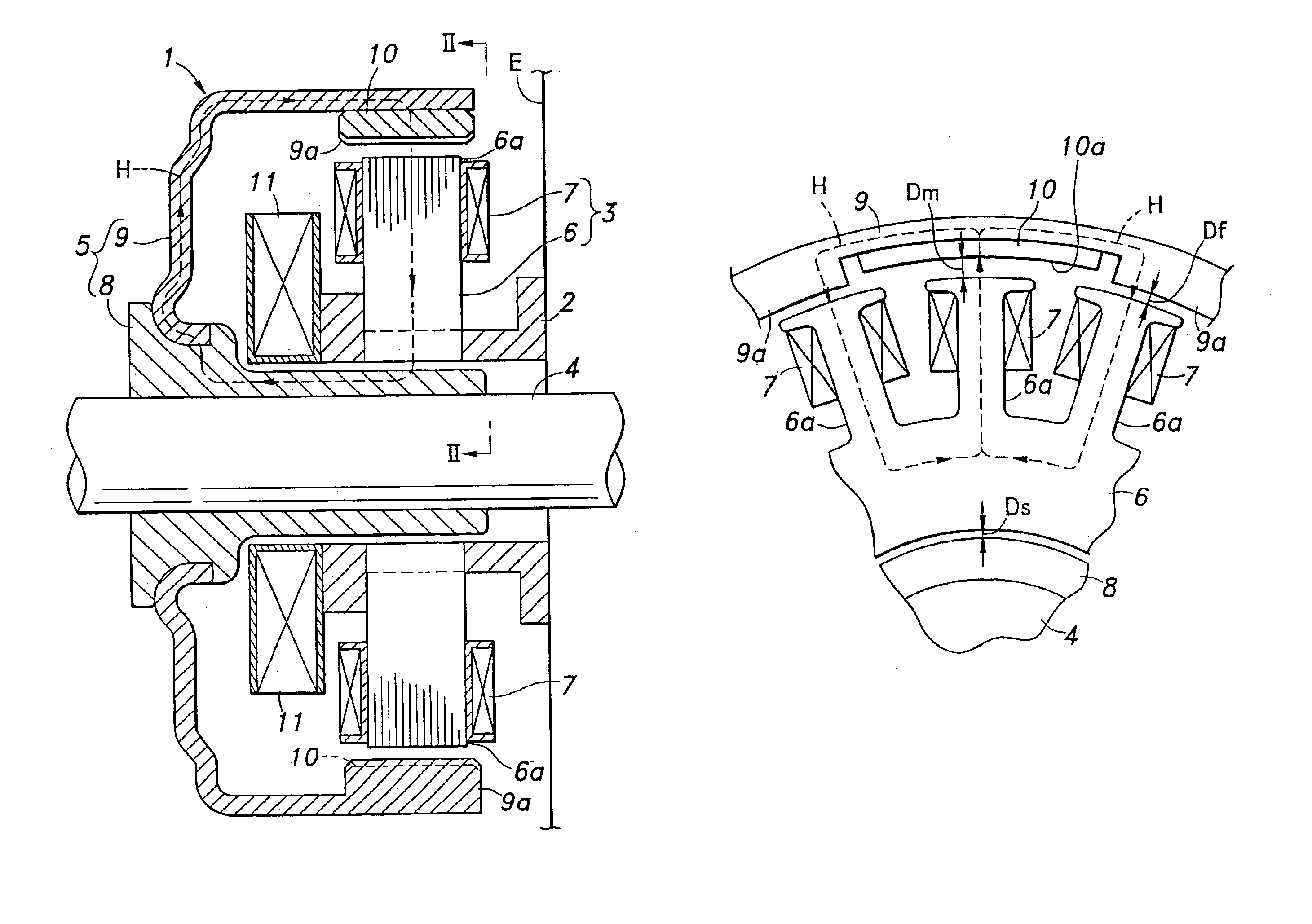
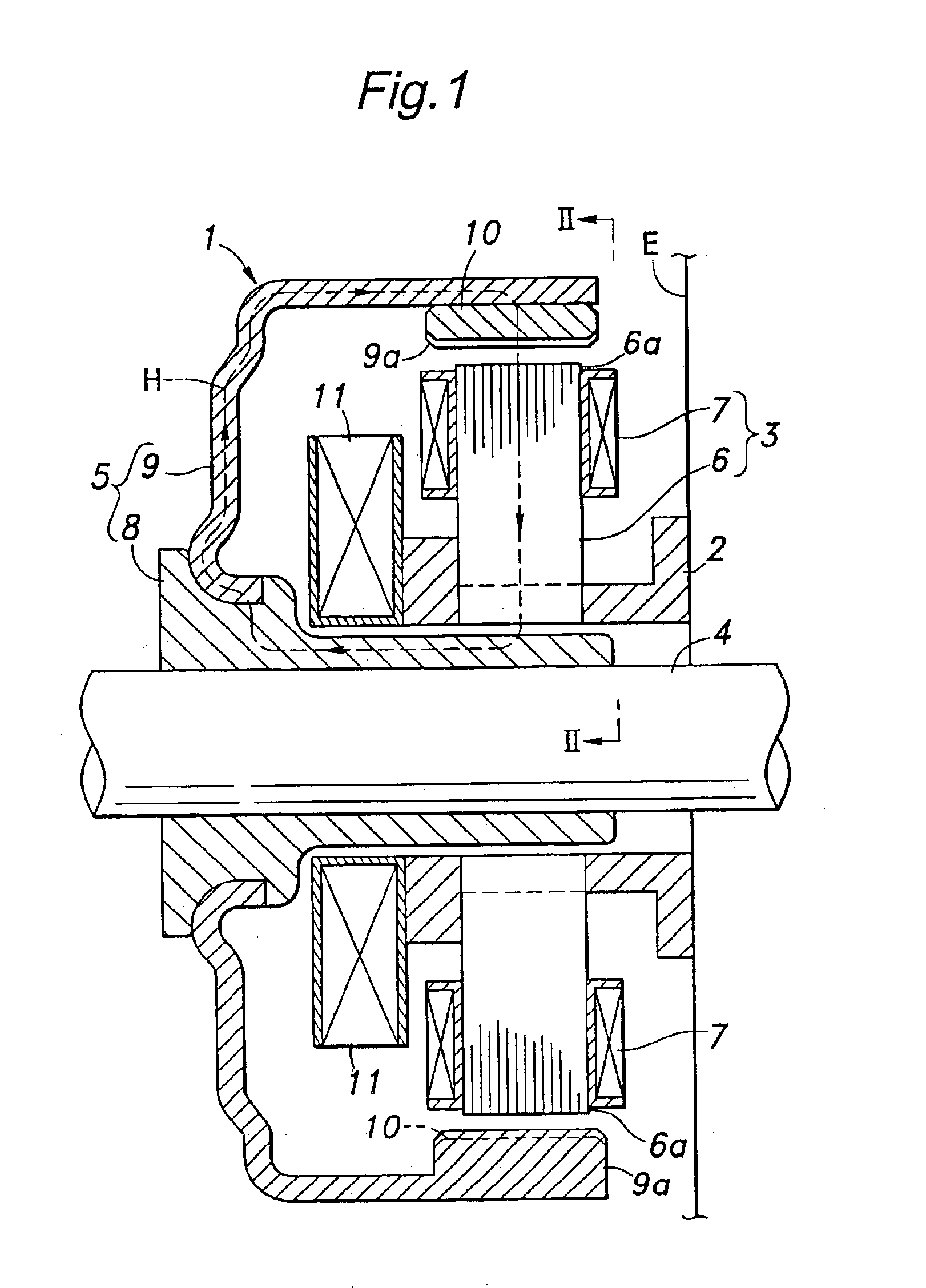
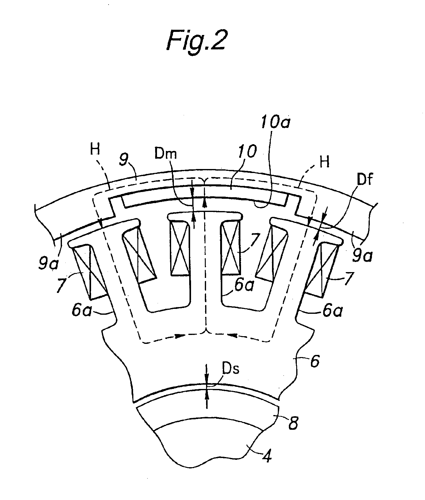
[0045]FIG. 7 shows the present invention which is applied to a generator using a slightly different yoke. In FIG. 7, the parts corresponding to those of the previous embodiments are denoted with like numerals without repeating the description of such parts. As shown in FIG. 7, this generator consists of a stator 5 and a rotor 3. In this case, the rotor 5 serves as a field element, and the stator 3 serves as an armature. This generator is based on the hybrid field system, and comprises a field control coil 11, and iron poles 6a serving as control magnet poles similarly as the foregoing embodiments.

[0046]The rotor 5 comprises a boss member 8 which receives the crankshaft 4 of an engine, for instance, in a fixed manner, and a first yoke 9 fixedly attached to the outer surface of the boss member 8 of the rotor. The boss member 8 of the rotor 5 is made of magnetic material such as iron, and is provided with a cylindrical shape. The boss member 8 of the rotor receives the crankshaft 4 in ...


PUM


Abstract

In a rotating electric machine using permanent magnets and a field control coil, to allow the properties of the rotating electric machine to be readily changed and the rotating electric machine to be adapted to various applications even when it is made of common component parts, the field control coil is adapted to superimpose magnetic flux components of different intensities onto magnetic flux components that are supplied by the magnet poles and iron poles to the teeth, respectively. The magnetic flux components may be differentiated by placing each permanent magnet in a recess defined in an inner circumferential surface of the yoke, and defining each iron pole by a part of the yoke located between an adjacent pair of the permanent magnets in such a manner that the inner circumferential surface of each permanent magnet is lower than the said part of the yoke.

Description

[0001]The present application claims priority from International Application PCT / JP02 / 03030 filed on Mar. 28, 2002, which in turn claims priority from Japanese Application 2001-092765, filed on Mar. 28, 2001.TECHNICAL FIELD[0002]The present invention relates to an electric rotating machine using permanent magnets for forming an electric field, and in particular to an electric rotating machine suitable for use as a starter / generator which can be used both as a starter motor for starting an internal combustion engine and as a generator once the engine has started.BACKGROUND OF THE INVENTION[0003]A vehicle engine is typically provided with a starter motor for starting the engine and a generator for generating electricity once the engine has started, and the accessories of the engine can be made compact and light in weight if these two pieces of equipment are combined into a single unit. Based on such a view point, various proposals have been made to use an electric motor also as a gene...

Claims


Application Information

Patent Timeline
IPC IPC(8): H02K1/27H02K19/12H02K21/04H02K21/22
CPCH02K11/048H02K19/12H02K21/046H02K21/22H02K1/2786H02K1/2791
Inventor YODA, TAKESHIKIMURA, YUMIKOUCHIYAMA, HIDEKAZU
Owner MITSUBA CORP
Features
  • Generate Ideas
  • Intellectual Property
  • Life Sciences
  • Materials
  • Tech Scout
  • Unparalleled Data Quality
  • Higher Quality Content
  • 60% Fewer Hallucinations
Learn More