Optical films having matt property, films having a high transmittance, polarizing plates and liquid crystal display devices

a technology of optical films and matt properties, applied in the direction of polarizing elements, instruments, ways, etc., can solve the problems of deterioration in display quality, decreased transmission rate of backlight in this method, and unsatisfactory improvement effect, etc., to prevent deterioration of display grade, high transmittance and matt properties

Inactive Publication Date: 2005-12-20
FUJIFILM CORP
View PDF4 Cites 11 Cited by
  • Summary
  • Abstract
  • Description
  • Claims
  • Application Information

AI Technical Summary

Benefits of technology

[0015]It is an object of the present invention to provide an optical film of matt property and a film having a high transmittance and matt property capable of preventing deterioration of display grade (non-uniformity of display or brightness, etc.) without causing lowering of display brightness, and a polarizing plate (a deflecting plate) of matt property as well as a liquid crystal display device using the film.

Problems solved by technology

In some of the light tuning films, there exists a unique brightness non-uniformity, thus bringing about deterioration in their display quality.
However, control of the concave-convex pattern was not as yet controlled so that a satisfactory improved effect has not been obtained.
Moreover, the transmission rate of backlight is decreased in this method due to scattering of the concave-convex surface to incur lowering of brightness for display.
In case such film is used as the aforesaid light tuning film, defect or strain is formed to deteriorate display quality.
In view of the foregoing, a liquid crystal display device employing a conventional optical film of matt property failed to be satisfactory in display brightness and display quality.
However, STN-LCD has problems such as a slow response (several hundred milliseconds) and difficulty in grade display, and is inferior as compared with a liquid crystal display characteristics using active device (such as TFT-LCD and MIM-LCD).
Since TN-LCD changes display colors and display contrast according to a viewing angle of looking at the liquid crystal display device (viewing angle characteristics), it involves a problem that the device is difficult in watching as compared with CRT.
As such sheet requires an extremely complicate stretching treatment, however, it is extremely difficult to manufacture a uniform optical compensative sheet of a large area stably according to this method.
As the liquid crystalline polymer fails to show a satisfactory direction on the alignment layer, however, it is impossible to enlarge the viewing angle in all directions.
However, the liquid crystalline polymer is devoid of birefringence so that it is unable to enlarge the viewing angle in all directions.
With the optical compensative sheet alone, however, a Newton ring caused by contact with the light tuning film and a non-uniformity in brightness caused by the light tuning film cannot be improved.

Method used


Image

  • Optical films having matt property, films having a high transmittance, polarizing plates and liquid crystal display devices
  • Optical films having matt property, films having a high transmittance, polarizing plates and liquid crystal display devices
  • Optical films having matt property, films having a high transmittance, polarizing plates and liquid crystal display devices

Examples


first embodiment

The First Embodiment

[0084]A basic construction of the optical film possessing matt property, the film having a high transmittance, and the liquid crystal display device using the films of the present invention are explained hereunder, referring to the drawings.

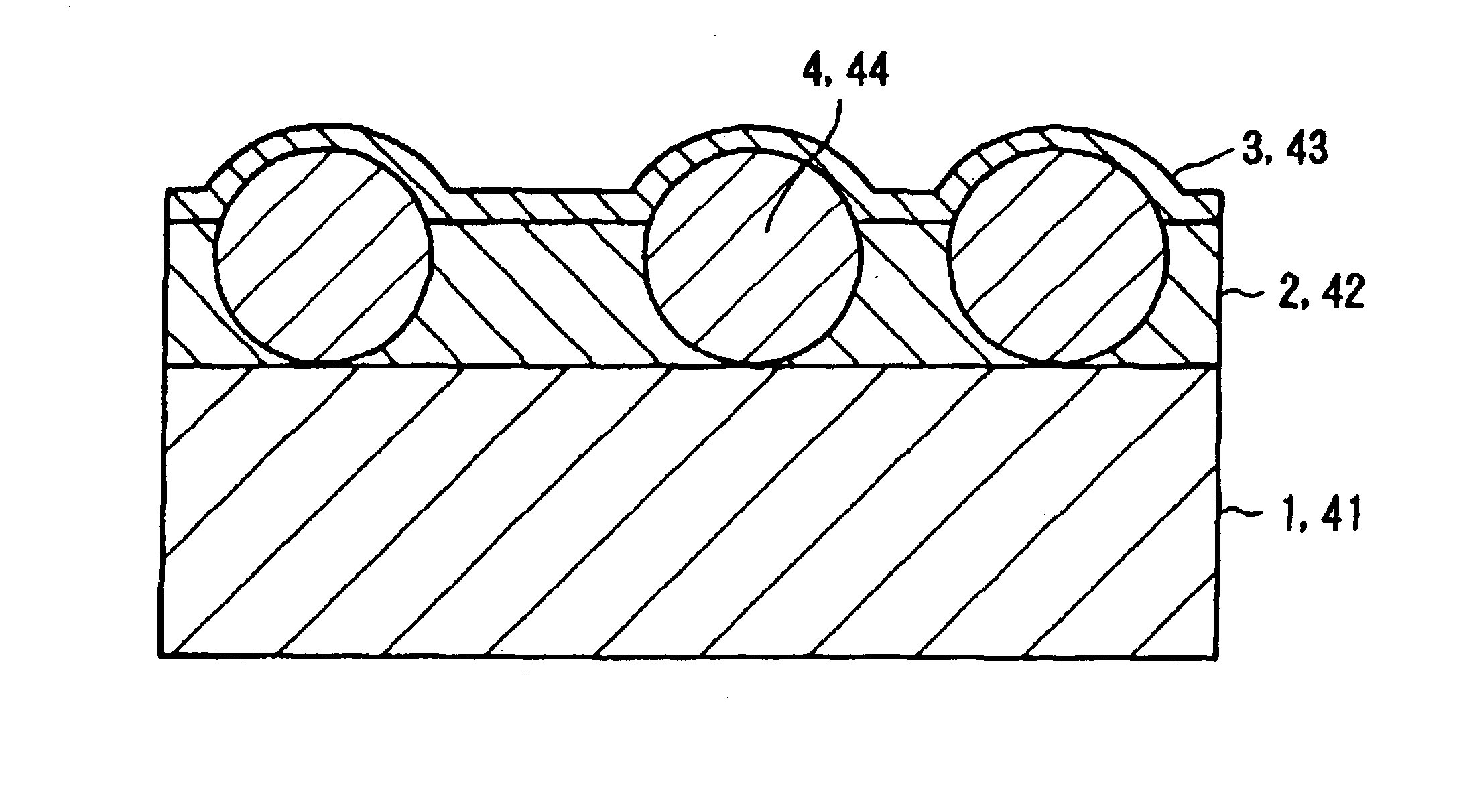
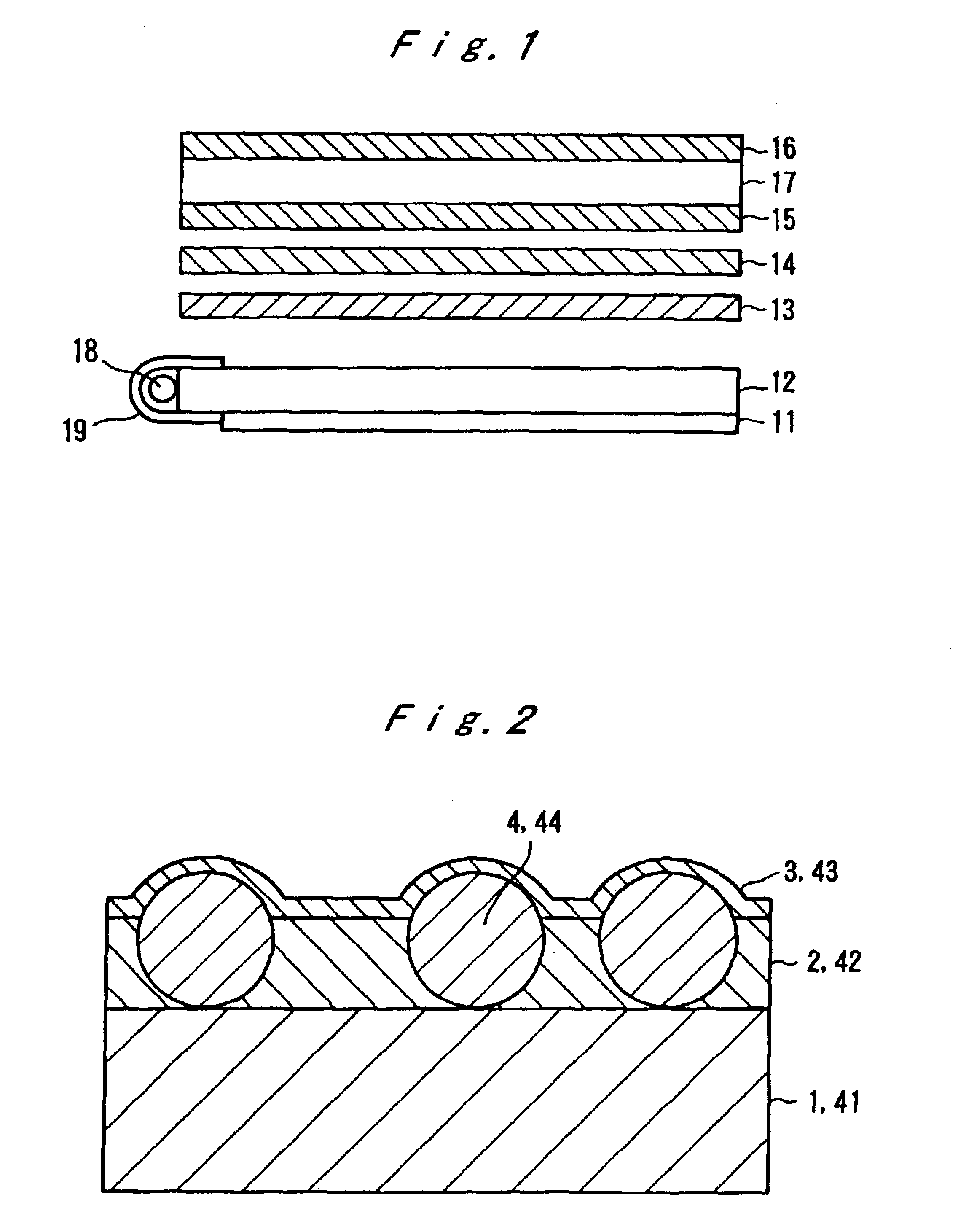
[0085]FIG. 2 is a schematic cross sectional view showing the layer construction of the film having a high transmittance and matt property according to the aforesaid paragraph (10).

[0086]The film having a high transmittance and matt property has a layer construction in the written order of a transparent support 1, a hard coat layer 2 and a layer having a low refractive index 3. The hard coat layer contains matt particles 4 which form a concavo-convex structure on the surface and impart haze to the film. The particles 4 has a particle diameter preferably 1.0˜15.0 μm, more preferably 3.0˜10.0 μm, and as is evident from FIG. 2, the particle 4 is preferably larger in particle diameter than the thickness of the hard coat layer 2.

[00...

second embodiment

The Second Embodiment

[0120]The optical film of matt property and the film having a high transmittance as well as a liquid crystal display device using these films of the second embodiment are significantly featured by incorporating specific fine particles into the optical film. More precisely, monodisperse transparent fine particles having an average particle diameter greater than the thickness of the hard coat layer and a particle diameter distribution of not more than 0.2 in terms of a variation coefficient and inorganic fine particles having been treated on the surface thereof with a silane-coupling agent are employed.

[0121]The transparent fine particles having an average particle diameter greater than the thickness of the hard coat layer are allowed to be present as particles of matt property. Illustrative of the particles of matt property to be incorporated are fine particles powder of inorganic substances such as silicon dioxide, titanium dioxide, magnesium oxide, calcium carb...

third embodiment

The Third Embodiment

[0143]A basic construction of the polarizing plate having a high transmittance, matt property and the optical compensative capacity as the third embodiment of the present invention and a liquid crystal display device using the polarizing plate will be explained with reference to the drawings.

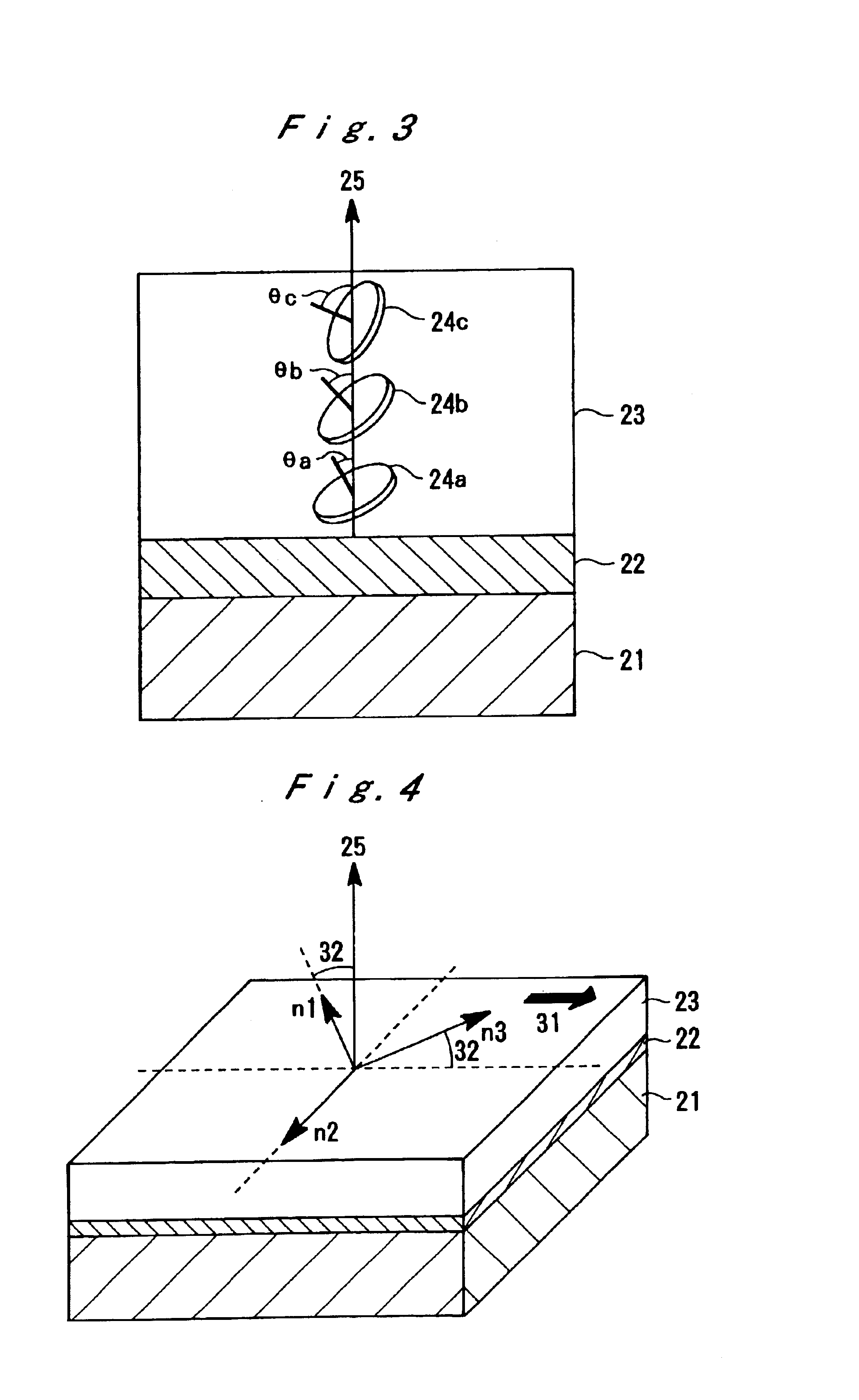
[0144]FIG. 3 is an example of a schematic cross sectional view showing the layer construction of the optical compensative layer. The optical compensative layer has a layer construction of a transparent support 21, an alignment layer 22, and an optical anisotropic layer 23 in the written order. The optical anisotropic layer contains liquid crystalline discotic compounds 24a, 24b and 24c and their light axes have inclined angles of θa, θb and θc with the direction of a normal line 25 of the transparent support. These inclined angles are increased from the transparent support side of the optical anisotropic layer toward the surface side thereof.

[0145]FIG. 4 shows optical charact...


PUM

PropertyMeasurementUnit
surface roughness Raaaaaaaaaaa

Abstract

The present invention relates to an optical film having matt property and a matted film having a high transmittance which can be used for producing polarizing plates or liquid crystal display device excellent in display brightness and display quality by using the aforesaid films adjusted in a specific surface roughness or by using a specific two kinds of fine particles in a hard coat layer of the films. The present invention relates also to a polarizing plate of a high transmittance having an optical compensative capacity and matt property. A liquid crystal display device and a color liquid crystal display device using the aforesaid polarizing plate possessing an excellent viewing angle characteristics and is improved in Newton ring caused by contact with a light-tuning film and in non-uniformity in brightness due to the light-tuning film.

Description

[0001]“This Application is a divisional of application Ser. No. 09 / 618,804, now U.S. Pat. No. 6,559,915, patented on May 6, 2003.FIELD OF THE INVENTION[0002]The present invention relates to an optical film possessing matt property, a film having a high transmittance, a polarizing plate using the films and a liquid crystal display device using these elements.[0003]The present invention relates also to a polarizing plate of a high transmittance possessing matt property and an optical compensative capacity and a liquid crystal display device and a color liquid crystal display device.BACKGROUND OF THE INVENTION[0004]The construction of a liquid crystal display device in conventional art is shown in FIG. 1. An ordinary liquid crystal display device is comprised of a backlight 11 of an edge light type on the furthest back surface and, in the order from the furthest back surface, a light introductive plate 12 for injecting light from the back light toward the surface, a scattering sheet 13...

Claims


Application Information

Patent Timeline
Patent Type & Authority Patents(United States)
IPC IPC(8): G02F1/1335G02F1/13357G02F1/13363
CPCG02F1/133504G02F1/1336Y10T428/24372G02F1/13363Y10T428/10G02F1/133606C09K2323/00
Inventor AMIMORI, ICHIROWATANABE, HIDETOSHIWATANABE, JUNINOUE, HIROSHI
Owner FUJIFILM CORP
Why Eureka
Try Eureka