Telescopic jib for a vehicular crane

a vehicular crane and telescopic technology, applied in the direction of buildings, buildings, constructions, etc., can solve the problems of increasing the overall weight of the jib, reducing the load bearing capacity of the jib, and not competing with the stiffness of rectangular trussed structures, etc., to achieve the effect of reducing the overall weight of the jib, and reducing the overall weight of the j

Inactive Publication Date: 2005-12-27
MANITOWOC CRANE GROUP FRANCE
View PDF13 Cites 7 Cited by
  • Summary
  • Abstract
  • Description
  • Claims
  • Application Information

AI Technical Summary

Benefits of technology

[0015]According to a preferred feature of the invention, the endmost segments of the upper and the lower profile parts comprise ends formed as straight legs such that the straight leg ends of the upper and lower profile parts can be welded to each other. This results in optimum force transfer from the upper profile part onto the lower profile part and vice versa, depending on the type of load. The welding joint between the lower profile part and the upper profile part is preferably maintained in the area of the neutral zone of the cross section of the jib. This arrangement is facilitated by the structure according to the invention. Since the curved shell segments abutting each other at an obtuse angle in the upper profile part provide a higher level of resistance to bending, the upper profile part can extend further downwardly into the area occupied, in the prior art jibs, by the lower profile part without adversely affecting the load bearing capacity of the jib. As a result it is easily possible to provide the welding joint between the upper profile part and the lower profile part in the area of the neutral zone of the jib cross section.
[0016]Rotation of the telescopic parts with respect to each other as a result of t

Problems solved by technology

Although such totally round lower profile parts have good load introduction and stability properties, they do not compete with rectangular trussed structures with respect to stiffness.
However, the drawback in such profile designs is that, due to the straight strips employed, the load introduction and stability properties which are particularly advantageous for curved profiles become poorer.
Additional stiffeners or thicker material gauges are again needed which disadvantageously increases the overall weight of the jib.
A disadvantage of this configuration is that planar plate segments or wall sections in such profiles strained by bending and buckling are weak points precisely with respect to buckling resistance.
A further disadvantage of the planar segments is that, in the force introduction area between the points of overlap between adjacent jib sections, the planar strips or plates segments are substantially less able than curved shells

Method used


Image

  • Telescopic jib for a vehicular crane
  • Telescopic jib for a vehicular crane
  • Telescopic jib for a vehicular crane

Examples


first embodiment

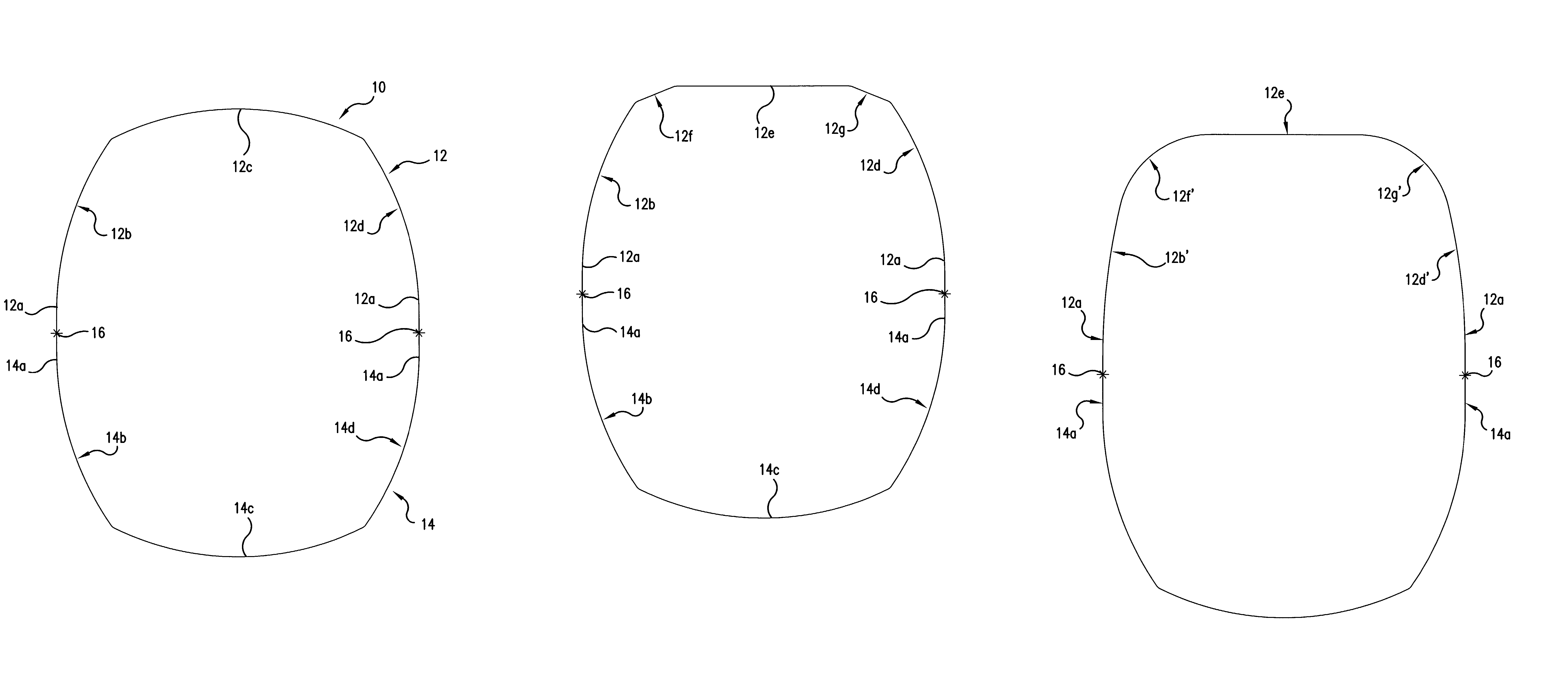
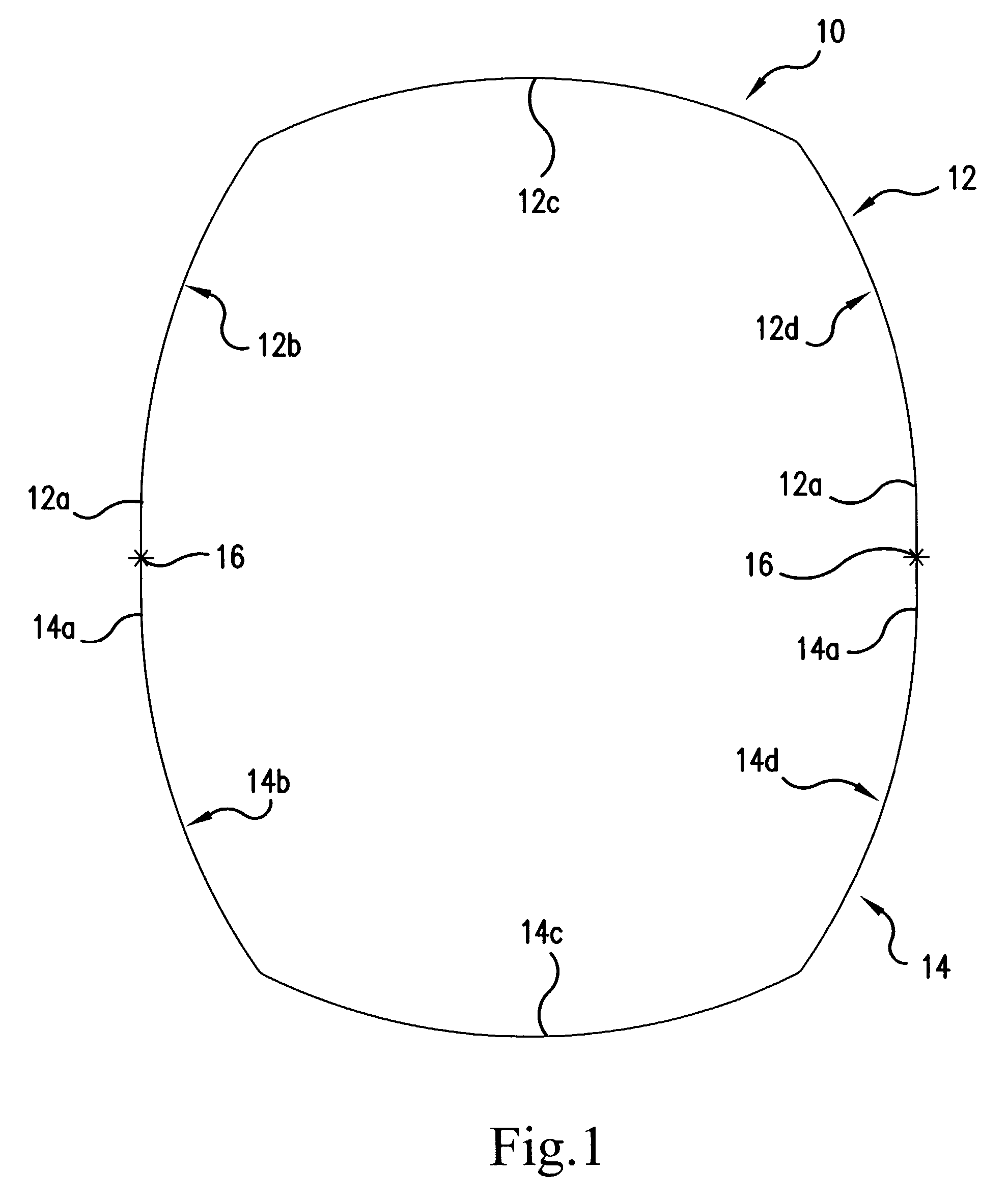
[0025]a telescopic jib section is shown in FIG. 1, generally indicated by the reference numeral 10. FIG. 1 is a sectional view of the jib section along the main axis thereof. As noted above, this section may be either the base section of a jib or a telescopic section.

[0026]The jib section of FIG. 1 consists of an upper profile part 12 and a lower profile part 14. The free leg ends 12a and 14a of the two profile parts 12, 14 are straight and are welded to each other at their end portions. The respective welding joints are indicated by the reference numerals 16. Welds 16 are situated in the neutral zone of the jib section. As is apparent, the upper profile part 12 and the lower profile part 14 have about the same vertical height.

[0027]The lower profile part is formed by three outwardly curved shell segments 14b, 14c and 14d. Each section 14b, 14c and 14d has the shape of a circular arc, though with respectively different radii of curvature. Segments 14b and 14d each include one of the...

third embodiment

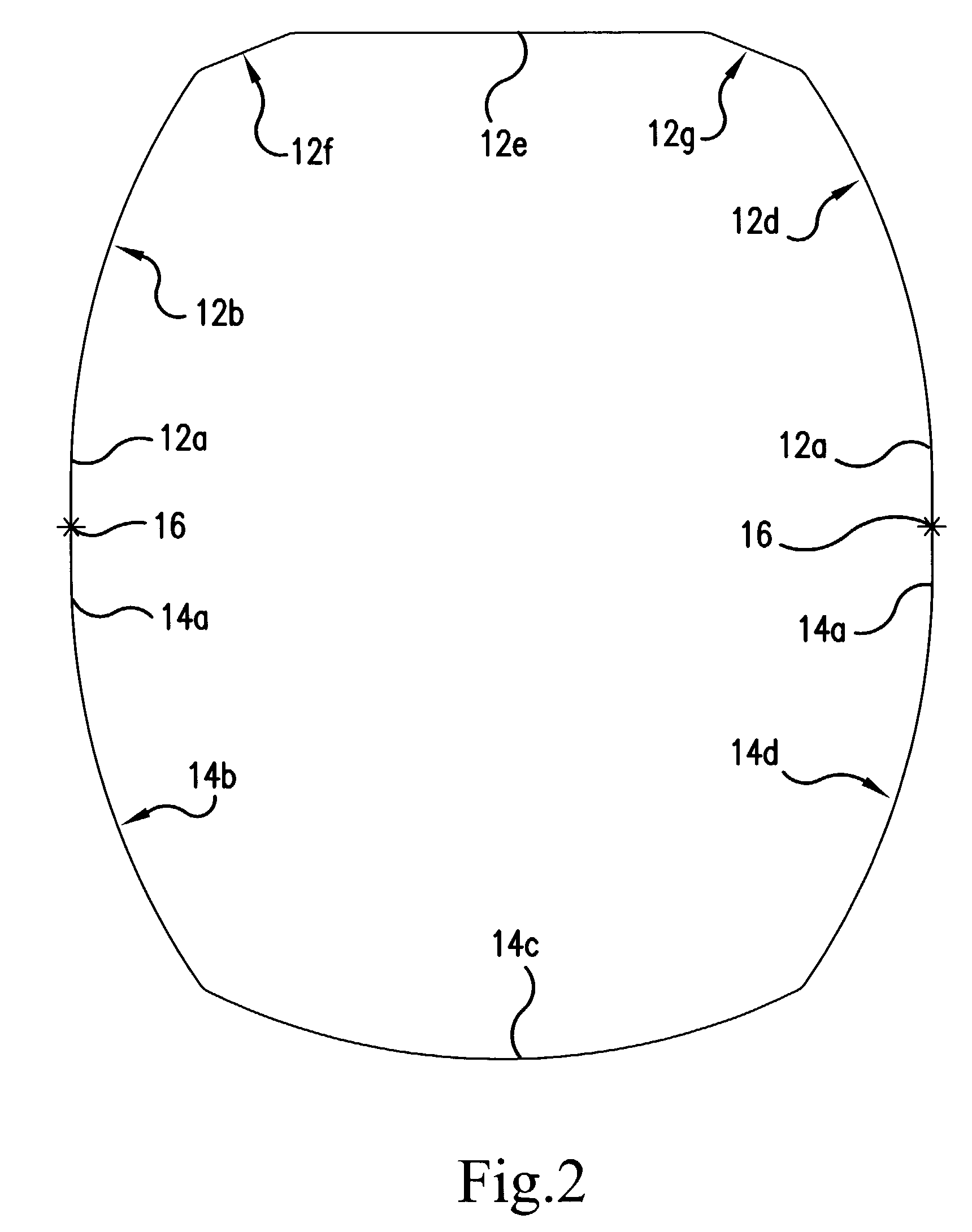
[0033]FIG. 3 illustrates in cross-sectional view the shape of a jib according to the present invention. Like the embodiment of FIG. 2, the embodiment of FIG. 3 includes a flat or straight segment 12e. Segment 12e is joined at its ends to outwardly curved shell segments 12g′ and 12f′ at the right and left upper corners of the upper profile part 12. Curved segments 12g′ and 12f′ have a relatively small radius of curvature. Segments 12g′ and 12f′ merge tangentially into the central straight shell segment 12e on one side and into the outwardly curved shell segments 12b′ and 12d′, respectively, on their other sides.

[0034]The outwardly curved segments of the jib provide excellent resistance to compressive forces. The relatively sharp “creases” formed at the joints where the curved segments meet at obtuse angles provide enhanced stiffness. This avoids any need for additional stiffeners, thus maintaining a desirably clean profile, desirably low overall weight and a compact nested jib struct...


PUM


Abstract

A telescopic jib for a crane, such as a vehicular crane, comprises an upper profile part and a lower profile part joined together. The lower profile part consists of several shell segments, each having an outwardly curved shape, and the upper profile part comprises several outwardly curved shell segments abutting each other at an obtuse angle.

Description

BACKGROUND OF THE INVENTION[0001]Telescopic jibs are used for cranes wherein the jib must be extended for use and retracted for other purposes, such as transport: Thus, such jibs are normally used for vehicular cranes. The sections of such jibs are typically tubular so that the successive sections can nest within each other when retracted and telescope outwardly to extend the jib to a desired length.[0002]Such telescopic jibs execute hoisting operations with the load at their front end. As a result, the jib is exposed to a bending force in two main axes. Viewing the jib in cross section along its longitudinal axis, each jib section, when loaded, is subject to tensile stress on the upper side of the jib while, on the lower side, compressive stresses occur. Due to lateral forces and eccentric loading, horizontal bending and torsion also occur.[0003]Designers of such jibs are principally interested in optimally configuring the cross-section for jib parts loaded in this way. Such a cros...

Claims


Application Information

Patent Timeline
IPC IPC(8): B66C23/687B66C23/693B66C23/70
CPCB66C23/701B66C23/70
Inventor PASCHKE, FRANZ
Owner MANITOWOC CRANE GROUP FRANCE
Why Eureka
Try Eureka