Fabrication method of semiconductor integrated circuit device
a technology of integrated circuits and fabrication methods, which is applied in the manufacturing of semiconductor/solid-state devices, basic electric elements, electric devices, etc., can solve the problems of difficult fine etching of copper series materials, reduce the size of wirings, and reduce the size of fabrications. , to achieve the effect of reducing the resistivity of wirings, reducing the size of wirings, and reducing the size of fabrications
- Summary
- Abstract
- Description
- Claims
- Application Information
AI Technical Summary
Benefits of technology
Problems solved by technology
Method used
Image
Examples
embodiment 1
(Embodiment 1)
[0079]In Embodiment 1, this embodiment of the invention is applied, for example, to a method of fabrication of a semiconductor integrated circuit device in which an nMISQn is formed in a p-well in a semiconductor substrate.
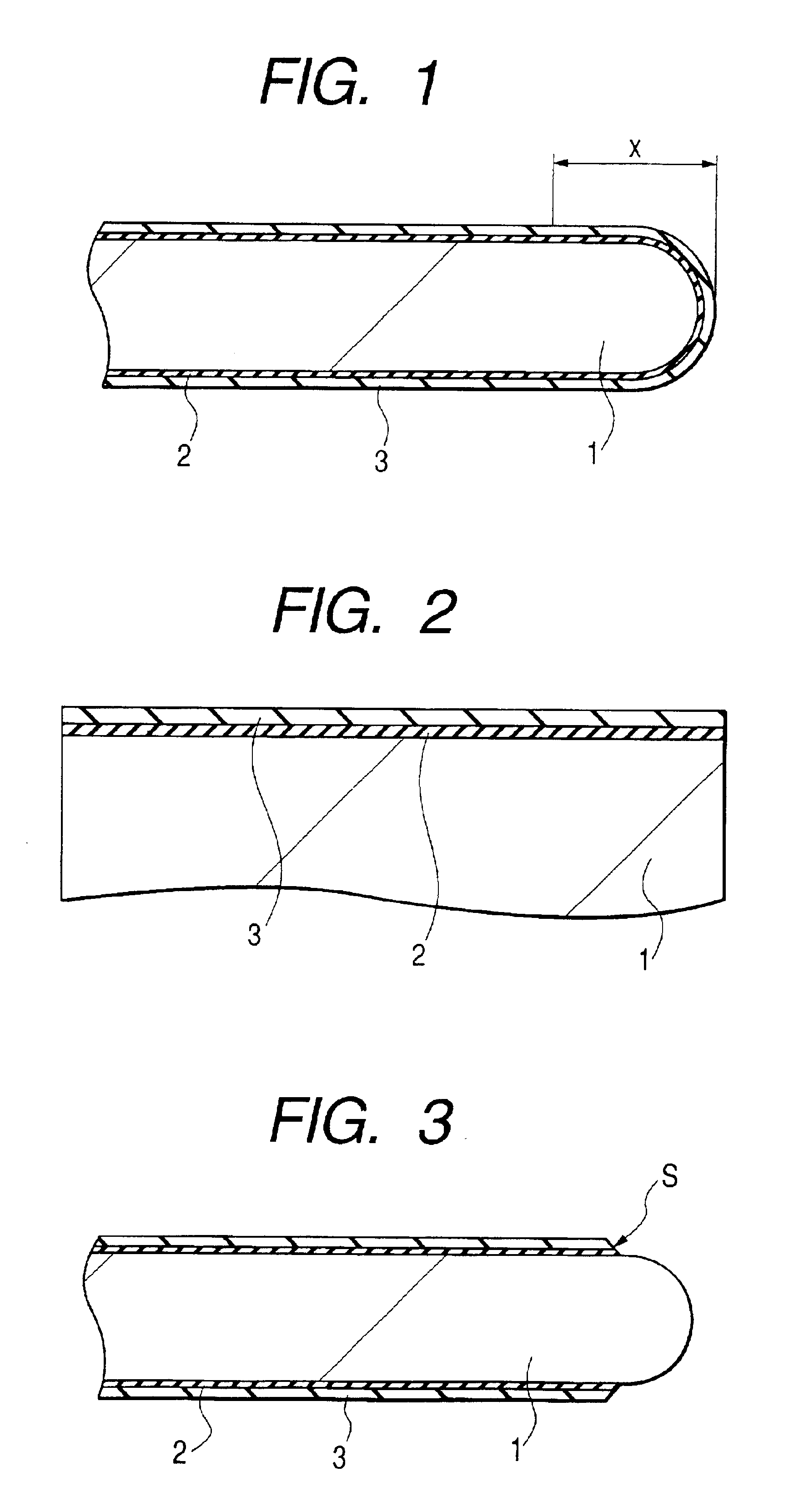
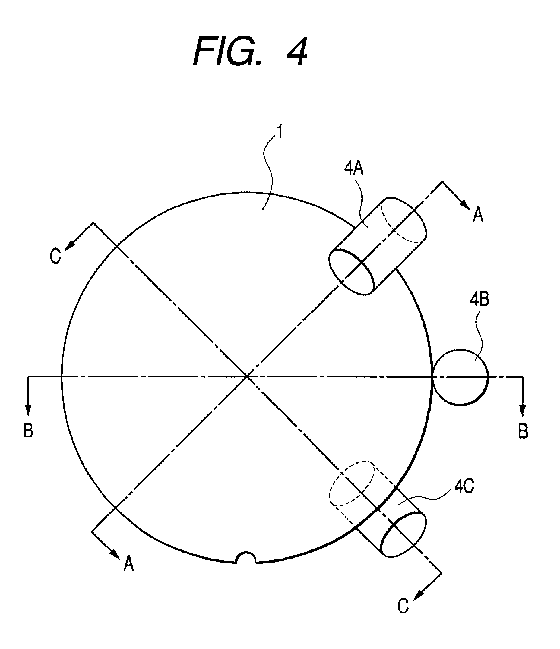
[0080]FIG. 1 and FIG. 2 are fragmentary cross sectional views of a wafer (semiconductor substrate) 1 of Embodiment 1. FIG. 1 shows, particularly, the vicinity of an edge of the wafer 1, and FIG. 2 shows, particularly, the vicinity of a device forming surface in the wafer 1 on an enlarged scale.
[0081]At first, as shown in FIG. 1 and FIG. 2, a wafer comprising a single crystal silicon (semiconductor substrate) 1 having a specific resistivity of about 10 Ωcm is provided. FIG. 2 is a fragmentary cross sectional view showing, on an enlarged scale, the vicinity of a device surface of the wafer 1. In Embodiment 1, the wafer has a thickness of about 750 μm and an outer periphery, in a rounded state of about 350 μm radius. Further, in Embodiment 1, the edge w...
embodiment 2
(Embodiment 2)
[0128]In Embodiment 2, thin films to be removed on the edge of the wafer are patterned before the removing step. Other components and fabrication steps are identical to those of Embodiment 1 as described above.
[0129]The method of fabrication of the semiconductor integrated circuit device of Embodiment 2 includes the same steps up to those that have been explained for Embodiment 1 with reference to FIG. 1 and FIG. 2.
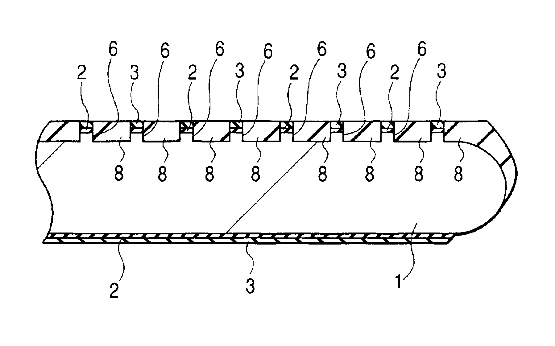
[0130]Then, as shown in FIG. 36, after coating the photoresist film 5 above the wafer 1, the photoresist film 5 is patterned by exposure using a mask. Successively, as shown in FIG. 37, the silicon nitride film 3 and the silicon oxide film 2 in the device isolation regions are removed by dry etching using the photoresist film 5 as a mask. Successively, grooves 6, each of about 350 nm depth, are formed above the wafer 1 in the device isolation region by dry etching using the silicon nitride films 3 as a mask.
[0131]Then, as shown in FIG. 38, the wafer 1 is hea...
embodiment 3
(Embodiment 3)
[0138]In the method of fabrication of a semiconductor integrated circuit device according to Embodiment 3, this invention is applied to a semiconductor integrated circuit device having wirings, for example, formed of Al (aluminum) or aluminum alloy.
[0139]The method of fabrication of the semiconductor integrated circuit device of Embodiment 3 includes the same steps as those explained with reference to FIG. 1 to FIG. 25 for Embodiment 1.
[0140]Subsequently, as shown in FIG. 44 and FIG. 45, a conductive film 22C (first conductive film), such as TiN, is deposited above the wafer 1 by a sputtering method. In FIG. 44, the conductive film 22C is not illustrated to provide easy understanding of the step for forming wirings on the silicon oxide film 16.
[0141]Successively, a conductive film 22D, for example, made of Al (first conductive film) is deposited on the surface of the conductive film 22C. Further, successively, a conductive film 22E, for example, made of TiN is deposite...
PUM
 Abstract
Description
Claims
Application Information
 - R&D
- Intellectual Property
- Life Sciences
- Materials
- Tech Scout
- Unparalleled Data Quality
- Higher Quality Content
- 60% Fewer Hallucinations
Browse by: Latest US Patents, China's latest patents, Technical Efficacy Thesaurus, Application Domain, Technology Topic, Popular Technical Reports.
© 2025 PatSnap. All rights reserved.Legal|Privacy policy|Modern Slavery Act Transparency Statement|Sitemap|About US| Contact US: help@patsnap.com


