Display device

a display device and display technology, applied in the field of display devices, can solve the problems of low contrast, lack of direct color modulation capability, and high cost of polarization management optics

Inactive Publication Date: 2005-12-27
HEWLETT PACKARD DEV CO LP
View PDF17 Cites 23 Cited by
  • Summary
  • Abstract
  • Description
  • Claims
  • Application Information

AI Technical Summary

Problems solved by technology

However, various implementation limitations may exist, including the lack of direct color modulation capability, low contrast, the high cost of polarization management optics, and relatively low response speed.

Method used


Image

  • Display device
  • Display device
  • Display device

Examples


Embodiment Construction

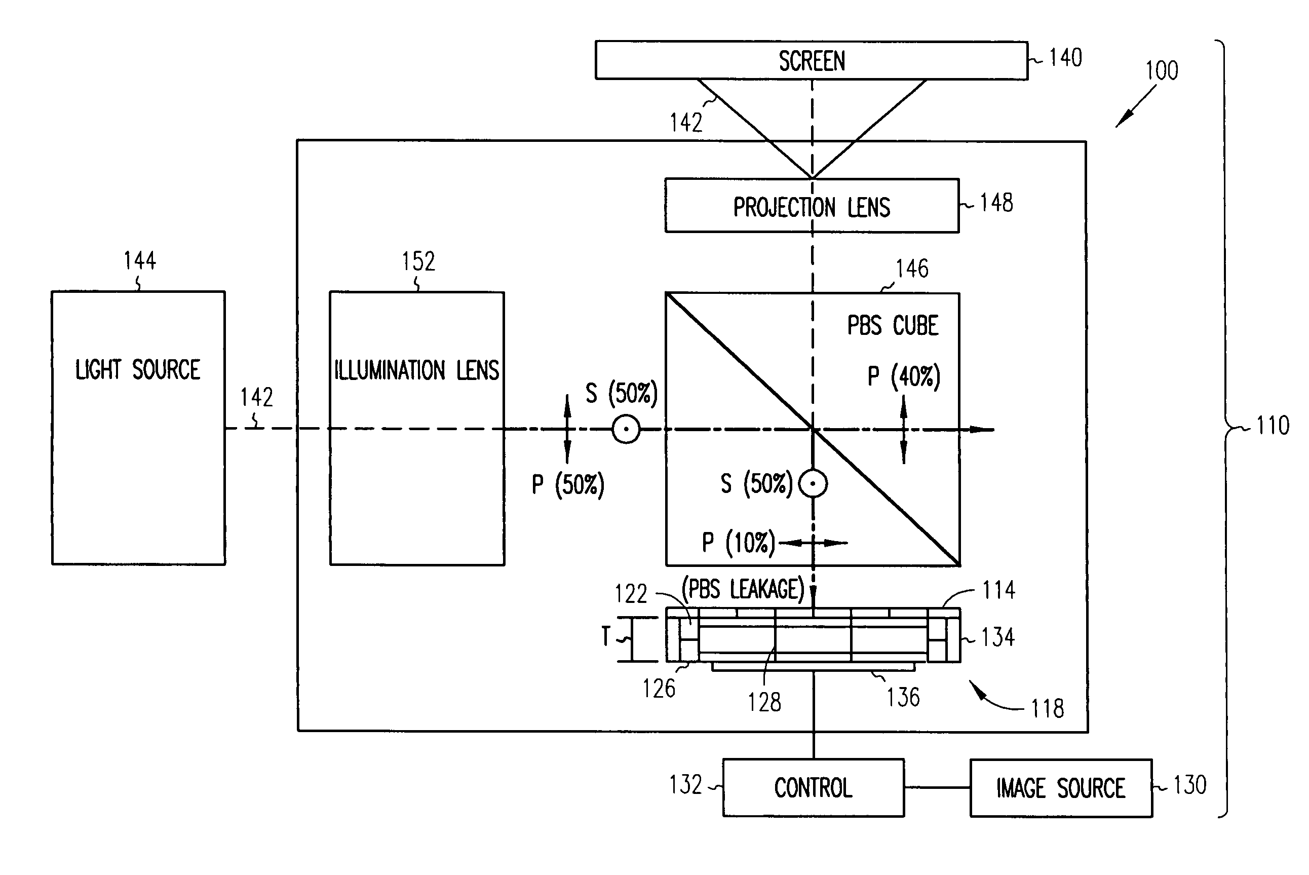
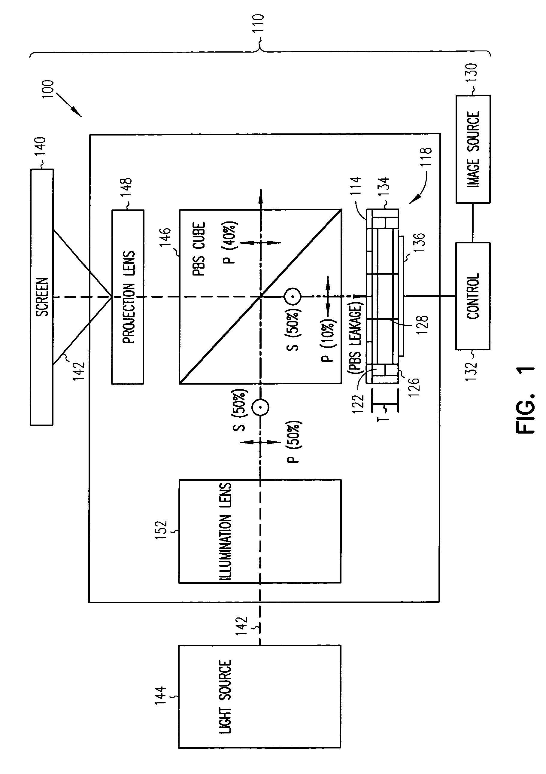
[0008]Liquid crystal microdisplays, including liquid crystal on silicon (LCoS) microdisplays used in polarization-based projector architectures, may provide a mediocre contrast ratio due to non-ideal polarization management and scattered or stray light in the projection engine. For example, non-ideal polarization management may be the result of stress birefringence in glass optics, skew ray angle depolarization in polarization beamsplitting (PBS) cubes, or low intrinsic contrast of the liquid crystal microdisplay itself. Such depolarizing effects may produce a black state that is too bright, thereby leading to poor contrast. Additionally, contemporary liquid crystal microdisplays lack the ability to modulate color directly.

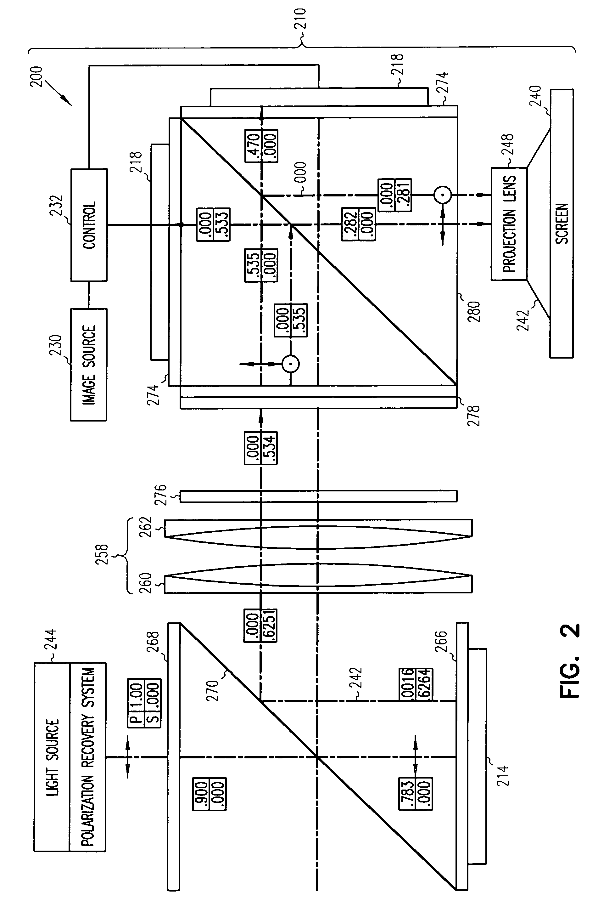
[0009]In some embodiments, an intensity modulator (e.g., a liquid crystal layer) may be used in conjunction with an intensity-color modulator (e.g., a variable absorption backplane) to address the challenges posed by using conventional liquid crystal microdisplays...


PUM

PropertyMeasurementUnit
refractive indexaaaaaaaaaa
optical propertyaaaaaaaaaa
distanceaaaaaaaaaa

Abstract

A method and apparatus includes receiving light at an intensity modulator. Subsequently, the light is received at an intensity-color modulator that includes at least one Fabry-Perot filter having a tunable optical property.

Description

RELATED APPLICATIONS[0001]This disclosure is related to pending U.S. patent application Ser. No. 10 / 428,261, titled “Optical Interference Pixel Display With Charge Control”, filed on Apr. 30, 2003, assigned to the assignee of the embodiments disclosed herein, the Hewlett-Packard Development Company, and incorporated herein by reference in its entirety.BACKGROUND INFORMATION[0002]The usefulness of liquid crystal devices, including LCoS (liquid crystal on silicon) display devices, may arise from a combination of small pixel size and high aperture ratio. High resolution (e.g., 1920×1080 pixel) liquid crystal based microdisplays are widely available. However, various implementation limitations may exist, including the lack of direct color modulation capability, low contrast, the high cost of polarization management optics, and relatively low response speed.BRIEF DESCRIPTION OF THE DRAWINGS[0003]FIG. 1 is a block diagram of an apparatus and a system according to various example embodimen...

Claims


Application Information

Patent Timeline
Patent Type & Authority Patents(United States)
IPC IPC(8): G02B26/00G02B27/28G02F1/01
CPCG02B26/001G02B27/283H04N9/3167G02B26/00G02B27/28G02F1/216H04N9/3197
Inventor GREER, MICHAELPIEHL, ARTHUR R.
Owner HEWLETT PACKARD DEV CO LP
Why Eureka
Try Eureka