High power density inverter and components thereof

a high-power density, inverter technology, applied in the direction of dc-dc conversion, power conversion systems, instruments, etc., can solve the problems of reducing the power conversion efficiency of the inverter, limiting the maximum power output, and damage to the switch and/or to a failure of the inverter, etc., to achieve the effect of being cheaply manufactured

Inactive Publication Date: 2005-12-27
INVERTERS UNLTD
View PDF58 Cites 7 Cited by
  • Summary
  • Abstract
  • Description
  • Claims
  • Application Information

AI Technical Summary

Benefits of technology

[0012]The present invention satisfies the need for a compact and inexpensively manufactured cooling apparatus, and methods of constructing the same, for use in the manufacture of high power-density inverters and in other devices having heat-generating chip packages. Accordingly, the inverter disclosed herein may include a compact and inexpensively manufactu

Problems solved by technology

Overheating of the switches often leads to damage to the switches and/or to a failure of the inverter.
The heat generated in the switches is wasted energy that reduces the power conversion efficiency of the inverter and tends to limit the maximum power-output, and hence the maxim

Method used


Image

  • High power density inverter and components thereof
  • High power density inverter and components thereof
  • High power density inverter and components thereof

Examples


Embodiment Construction

[0047]Although some embodiments of the present invention will be shown and described in detail, it should be understood that various changes and modifications may be made without departing from the scope of the appended claims. The scope of the present invention will in no way be limited to the number of constituting components, the materials thereof, the precise size and shapes thereof, the frequencies therein, the relative polarities, magnitude or ratio of voltages or currents therein, etc.

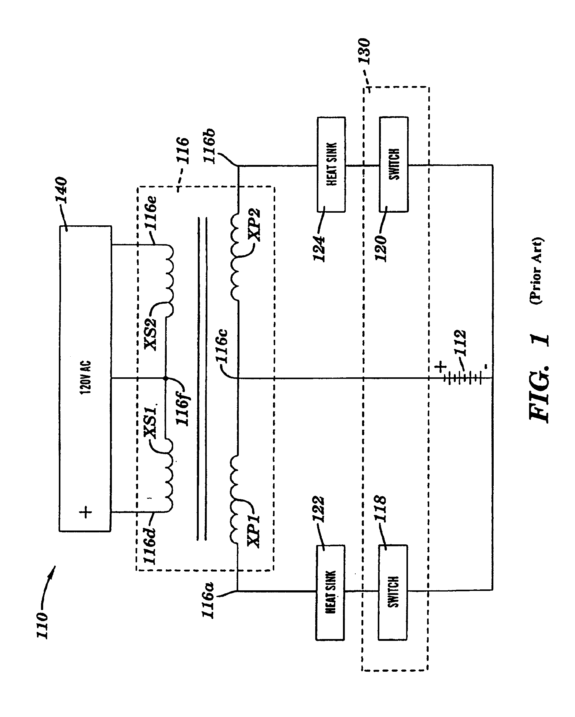
[0048]FIG. 1 is a reproduction of FIG. 2 of U.S. Pat. No. 6,038,156 and is therein described. The disclosure of U.S. Pat. No. 6,038,156 is hereby incorporated herein by reference. FIG. 1 depicts a circuit diagram of a related art push-pull inverter 110. The inverter has a center-tap (at node 116c) in the dual primary windings (e.g., windings XP1 and XP2) of the power transformer 116 and has a relatively large distance between the conductors (e.g., 116a and 116b) of the first and second primary w...


PUM


Abstract

A compact high-power pure-sinewave inverter amenable to mass manufacturing techniques. Methods for increasing the power rating, power density and/or power conversion efficiency of a sinewave-modulated pulse-width-modulated (PWM) inverter having a either half-bridge or full-bridge topology, including minimizing uncoupled inductances and loop inductances in the primary winding(s) by employing either ribbon-like conductors having a high crossectional aspect ratio or litz-wire. A compact linear heatsink adapted to cool a row of semiconductor devices (such as inverter switches) mounted on a high-current printed circuit board. Methods for inexpensive manufacture of a fluid-cooled linear heat sink. A transformer including a filter inductor core.

Description

BACKGROUND OF THE INVENTION[0001]1. Technical Field[0002]The invention relates generally to switching power conversion devices, and more specifically to high power-density DC-to-AC inverters.[0003]2. Related Art[0004]Growing public concern about the accelerating depletion of the Earth's supply of fossil fuels (e.g., crude oil) and of other contemporary non-renewable energy sources, and energy-related environmental concerns such as pollution and global warming due to emissions, have accelerated the development of alternative energy generation technologies (e.g., fuel cells, photovoltaics, wind power, biomass, tallow trees, etc.) for generating power. Growing concerns about the reliability of local, state and national power distribution infrastructures have promoted interest in on-site power generation technologies, particularly those which are compact enough to be maintained on a private premises while providing enough power to satisfy average power requirements of a home, of a busin...

Claims


Application Information

Patent Timeline
IPC IPC(8): H02M7/00
CPCH02M7/003
Inventor BHATE, SURESH K.CESTRA, JOHNHARRINGTON, CHRISTOPHER B.HOOGENBOOM, LEO
Owner INVERTERS UNLTD
Why Eureka
Try Eureka