Method for producing (Nb, Ti)3Sn wire by use of Ti source rods

a source rod and wire technology, applied in the direction of superconductors/hyperconductors, superconductors, connections, etc., can solve the problems of difficult fabrication, sub>sn composites, and so on, and achieve the effects of reducing the effective filament diameter and ac losses, good ductility, and high diffusion rate of ti

Active Publication Date: 2006-01-03
BRUKER OST LLC
View PDF15 Cites 20 Cited by
  • Summary
  • Abstract
  • Description
  • Claims
  • Application Information

AI Technical Summary

Benefits of technology

[0007]The present invention overcomes all of the problems indicated above. In accordance with the present invention Nb—Ti alloy or Ti rods (herein referred to as “Ti dopant source” rods) are distributed among rods of Nb or a Nb alloy with at least some Cu or Cu alloy intervening between rods. The number of Ti dopant source rods is small compared to the number of Nb or Nb alloy rods, and the dopant source rods are preferably symmetrically distributed among the more numerous Nb or Nb alloy rods. The invention can be used with the bronze process for Nb3Sn production, but is particularly applicable where the internal tin process is used. In one preferred embodiment Nb (or Nb alloy) rods are distributed in a matrix of Cu surrounding a pure Sn or SnCu alloy core and this subelement for the final multifilament wire is surrounded by a Ta or Nb or Nb alloy diffusion barrier. As will be further evident in the following, the term “subelement” refers to the subassembly which when tightly grouped (packed) with like subassemblies forms a precursor assembly for the final superconductor wire. The Ti dopant source rods in the subelement are evenly and symmetrically arranged amongst the Nb (or Nb alloy rods). Where the rods comprise Nb alloy, such alloy is comprised of not less than 70 wt % Nb. The possible concentration range for Ti in the Ti dopant source rods is from about 10 to 100% by weight. Particularly useful because of good ductility and ready commercial availability are Ti dopant source rods formed of the Nb47 wt % Ti alloy. The Ti from the Ti dopant source rods diffuses during heat-treatment from the Ti dopant source rods to the surrounding Nb or Nb alloy rods with the assistance of the Sn diffusion and the high diffusion rate of Ti through Cu—Sn alloy. The design of the exact volume ratio of Ti dopant source rods to Nb (or Nb alloy) rods is determined by the wt % of Ti in the Ti dopant source rods, the volume of Nb or Nb alloy rods, and the desired final Ti doping concentration. The Ti dopant source rods should be protected by a Nb diffusion barrier to prevent Cu—Ti intermetallic particle formation during process steps. A beneficial side effect of the Ti diffusion is that at the reaction stage the Ti source rods are replaced with Cu, which suggests designs (e.g. spokes of Ti source rods) of the subelement where the Ti source rods could act to subdivide superconducting regions, thereby reducing the effective filament diameter and AC losses.

Problems solved by technology

(Nb, Ta)3Sn composites are commonly made with Nb7.5 wt % Ta filaments, which are harder than the pure Nb filaments used in (Nb, Ti)3Sn composites and thus more difficult to fabricate.
However several problems arise in use of this conventional Sn—Ti alloy approach.
One problem is that hard, rod shaped Sn—Ti intermetallic particles of dimensions ˜25 μm diameter by ˜100 μm long are unavoidably formed during the casting of the Sn—Ti alloy.
The consequence is that the minimum diameter of the wire or the elements used in the wire is limited.
Furthermore the Sn—Ti alloy is difficult and expensive to produce.
Quality control is also an issue, which is especially problematic in light of the volumes of alloy that would be required to fulfill the wire orders for next generation fusion magnets.
The problem with this method is that it indeed requires every filament to have a Ti or Nb—Ti source in its center, which is prohibitively expensive.
The problem with this method is that is difficult to fabricate without cracking.

Method used


Image

  • Method for producing (Nb, Ti)3Sn wire by use of Ti source rods
  • Method for producing (Nb, Ti)3Sn wire by use of Ti source rods
  • Method for producing (Nb, Ti)3Sn wire by use of Ti source rods

Examples


example 1

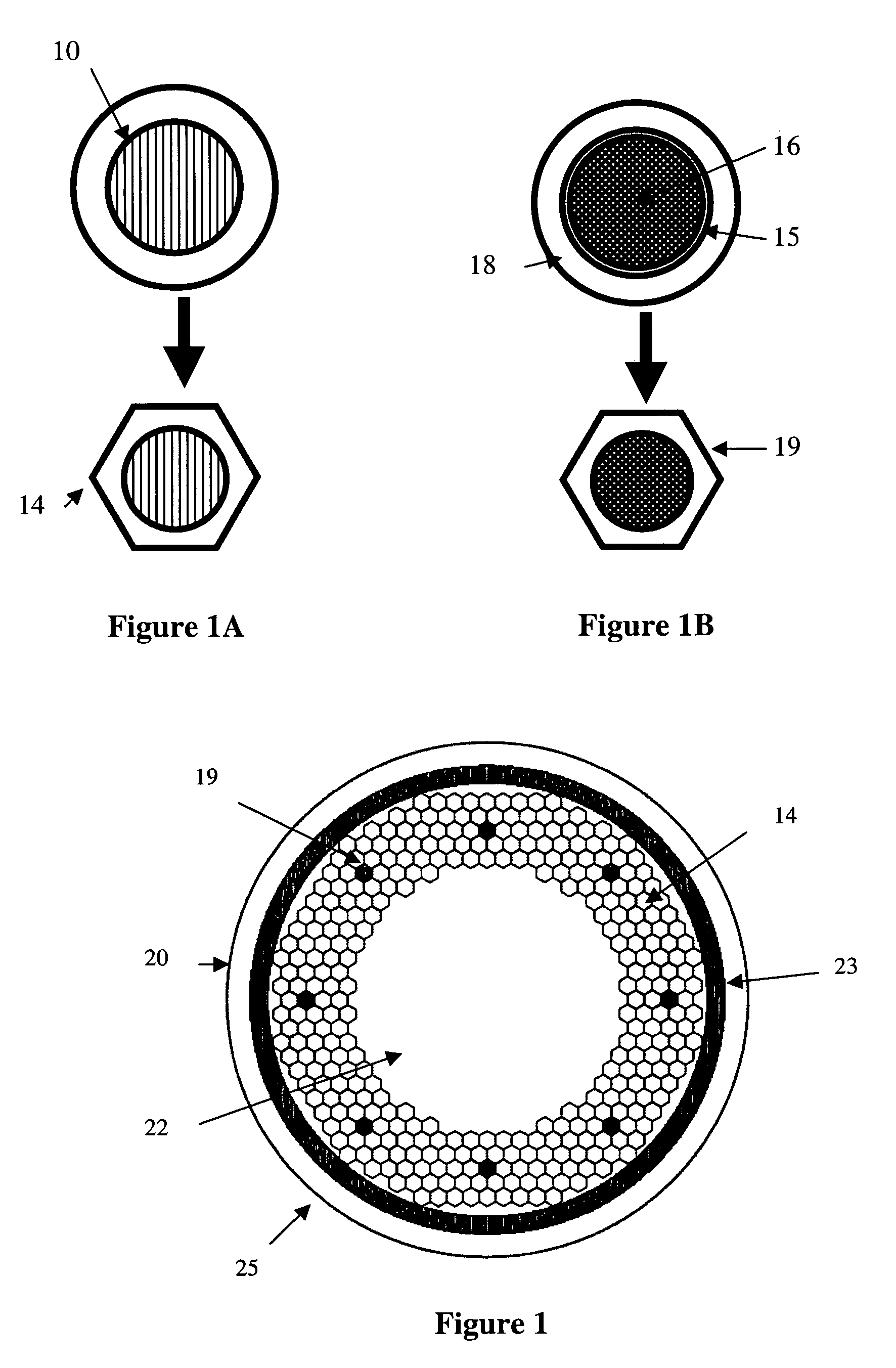
[0026]In this Example a wire was prepared using in the process subelements of the type shown in FIG. 1. The hex filament subelement design was thus used with a distributed reactable Nb diffusion barrier. It included three hot (≧900° F.) extrusions.

[0027]First Extrusion—Monofilament copper clad hexes of Nb were manufactured by extruding a Nb ingot in a copper can and drawing the resulting rod to hex rods for restacking (FIG. 1a). Typical dimensions of a hex rod are ⅛ inch flat-to-flat×2 feet in length. Monofilament hexes of Nb47 wt % Ti were manufactured by extruding a Nb47 wt % Ti (with a Nb diffusion barrier) in a copper can and drawing the resulting rod to hex rods for restacking with the Nb rods (as in FIG. 1a).

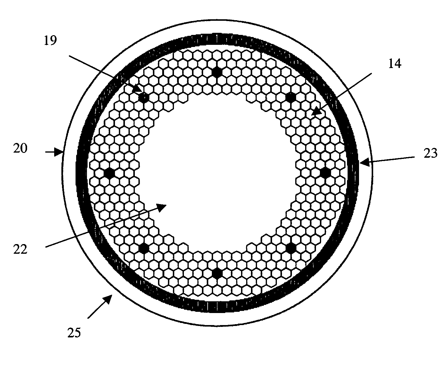
[0028]Second Extrusion—Referring to the cross-sectional view in FIG. 1b, the rods from the first extrusion were restacked in a Nb alloy barrier tube. The Ti dopant source rods were arranged in a symmetrical uniformly spaced pattern among the stack of copper clad Nb or Nb a...

example 2

[0031]In this Example a wire was prepared using in the process subelements of the type shown in FIG. 2. The round filament subelement design was thus used with a single, non-reacting Ta diffusion barrier. It featured one (≧900° F.) extrusion.

First Extrusion

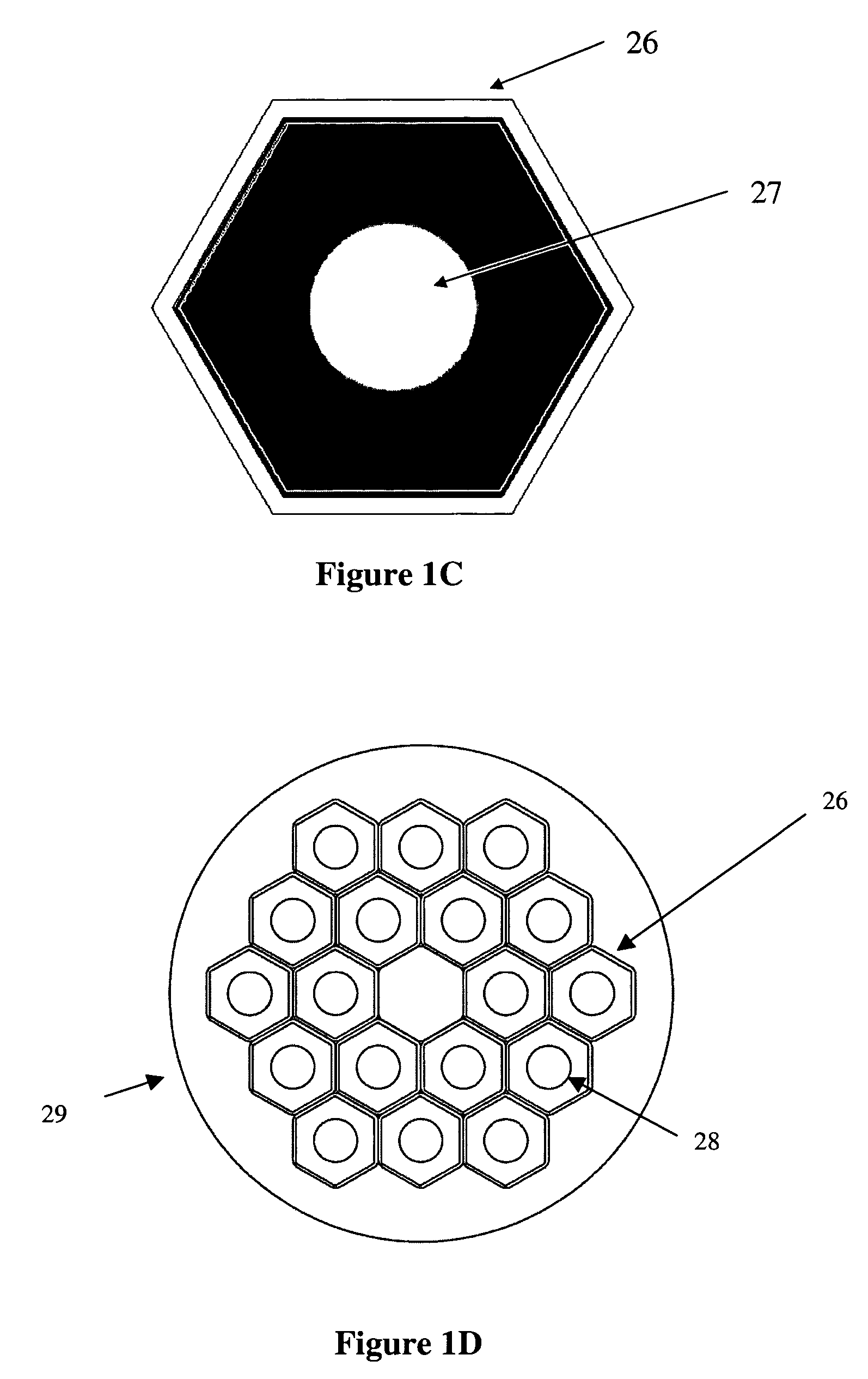
[0032]Nb rods and Nb47 wt % Ti rods (dia. 0.54 inches) are packed in a gundrilled copper billet (dia. 12.25 inches, FIG. 2a) and this subelement was extruded to 3.1 inches. Monofilament rods of Nb47 wt % Ti were manufactured in a similar manner to that described in Example 1.

[0033]This subelement was gundrilled and packed with tin, wiredrawn and shaped at restacking size.

Restack

[0034]The subelement shapes were packed in a Ta barrier in a Cu tube and drawn to final size (0.81 mm diameter). The wire was reacted (FIG. 6) using a typical internal tin heat treatment (210° C. for 48 hrs., 400° C. for 48 hrs., and 675° C. for 100 hrs). During the reaction stage both the filaments fully reacted and the titanium in the Nb47 wt % Ti rods di...


PUM

PropertyMeasurementUnit
diameteraaaaaaaaaa
sizeaaaaaaaaaa
sizeaaaaaaaaaa

Abstract

An improvement is disclosed in the method for producing a multifilament (Nb, Ti)3Sn superconducting wire by the steps of preparing a plurality of Nb or Nb alloy rods where Nb or Nb alloy monofilaments are encased in copper or copper alloy sheaths; packing the Nb or Nb alloy rods within a copper containing matrix to form a packed subelement for the superconducting wire; providing sources of Sn, and sources of Ti within said subelement; assembling the subelements within a further copper containing matrix; and diffusing the Sn and Ti into the Nb or Nb alloy rods to form (Nb, Ti)3Sn. The method is improved by diffusing the Ti into the Nb from a minor number of Ti dopant source rods which are distributed among the Nb or Nb alloy rods.

Description

RELATED APPLICATION[0001]This application claims priority from U.S. Provisional Application No. 60 / 512,354 filed Oct. 17, 2003.FIELD OF THE INVENTION[0002]This invention relates generally to methods for preparing superconductive wires and cables, and more specifically relates to a method for preparation of (Nb,Ti)3Sn.BACKGROUND OF THE INVENTION[0003]The addition of Ti or Ta to Nb3Sn is required to obtain the highest Bc2 (upper critical field) and highest critical currents at high (˜>12T) magnetic fields. (Nb, Ti)3Sn has lower AC losses than the alternative (Nb, Ta)3Sn material, therefore making it an appealing source for superconducting magnet makers concerned with rapidly changing magnetic fields. (Nb, Ti)3Sn also has better strain tolerance than (Nb, Ta)3Sn making it more useful in high stress magnet designs. (Nb, Ta)3Sn composites are commonly made with Nb7.5 wt % Ta filaments, which are harder than the pure Nb filaments used in (Nb, Ti)3Sn composites and thus more difficult t...

Claims


Application Information

Patent Timeline
Patent Type & Authority Patents(United States)
IPC IPC(8): H01L39/24B21C37/04C22C1/02C22F1/18
CPCB21C37/047C22C1/02H01L39/2409Y10T29/49014Y10S505/93Y10T29/49117Y10S505/928H10N60/0184C22F1/18
Inventor HONG, SEUNGPARRELL, JEFFFIELD, MICHAEL
Owner BRUKER OST LLC
Why Eureka
Try Eureka