

Magnetic fluid power generator device and method for generating power
- Summary
- Abstract
- Description
- Claims
- Application Information
AI Technical Summary
Benefits of technology
Problems solved by technology
Method used
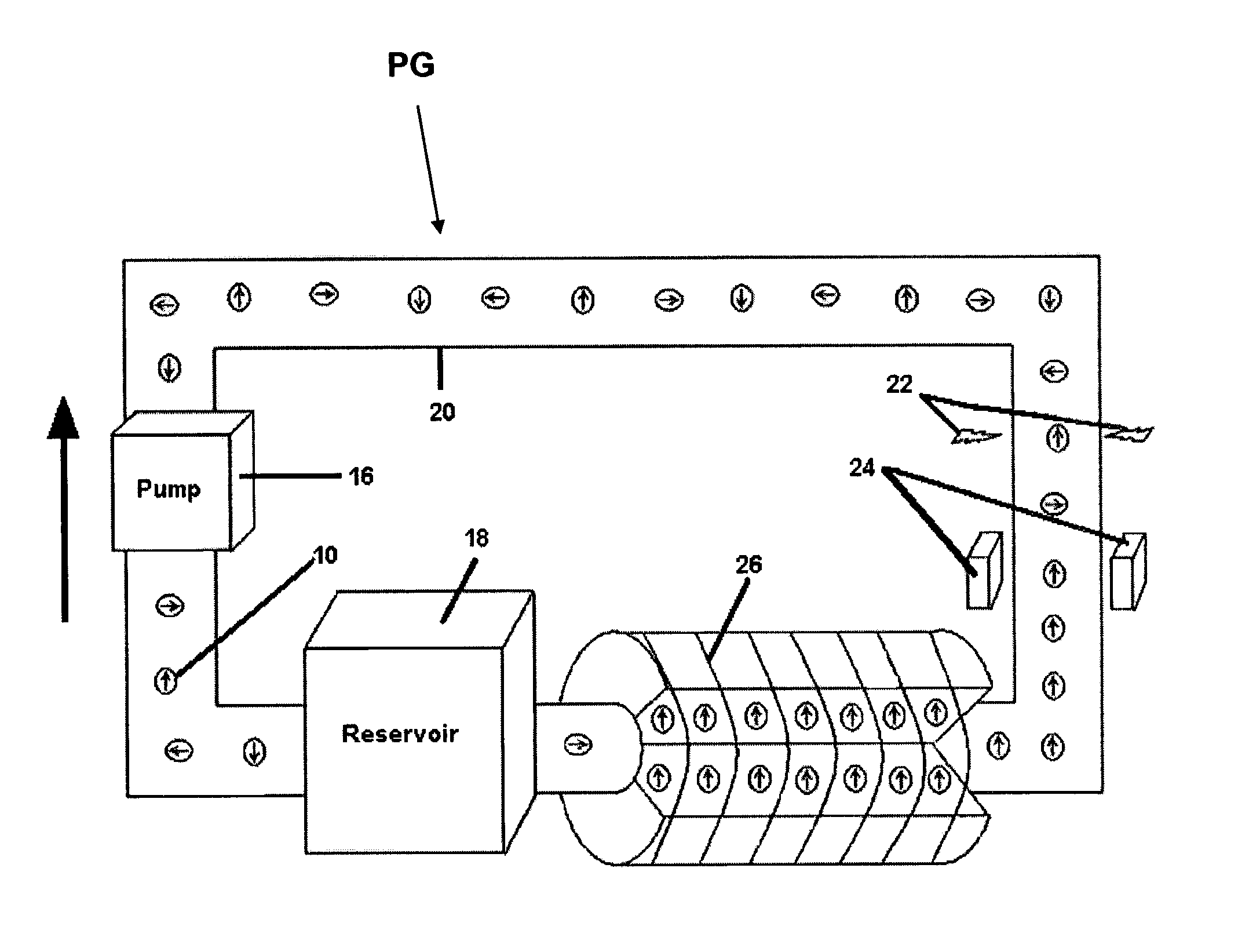
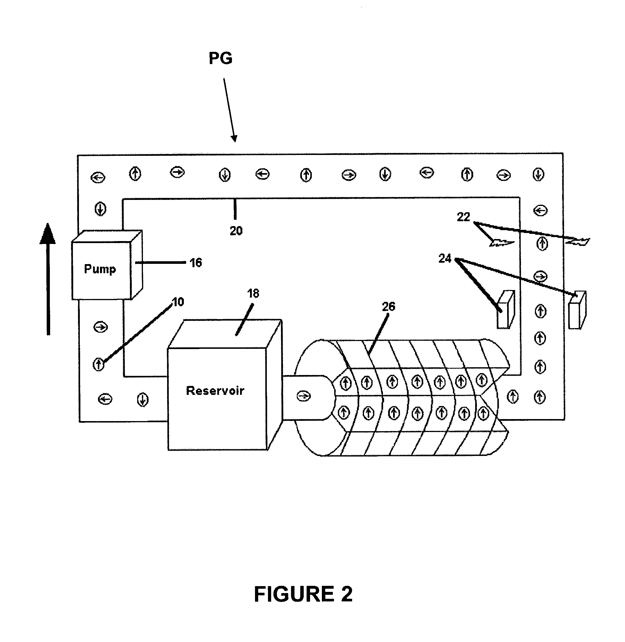
Image


Examples
example
[0027]Ultrafine powders of iron with a particle size less than about 20 nm were produced using the proprietary microwave plasma chemical synthesis process described in U.S. Pat. No. 6,409,851 by Sethuram et al. Vapors of iron pentacarbonyl were fed into the plasmatron with argon as the plasma gas. The plasma gas flow rate was about 0.003–0.0034 m3 / min and that of the carrier gas was about 0.0003–0.0004 m3 / min. The plasma temperature was about 900–950° C., the powder feed rate was about 50–60 gm / hr, and the quenching water flow rate was about 2.0–2.5 liter / min at 20° C. The reactor column diameter was about 48 mm and its length was about 10″. The microwave forward power was about 4 kW, the reflected power was about 0.7 kW, and the operating frequency was about 2450 MHZ.
[0028]The iron particles were coated with polyethylene glycol in solution phase and dispersed in water by high-speed shear mixing and ultrasonification.
PUM
 Abstract
Description
Claims
Application Information