Unlock instant, AI-driven research and patent intelligence for your innovation.

Fluid-solid contacting method

Inactive Publication Date: 2006-01-10
UOP LLC
View PDF8 Cites 0 Cited by
  • Summary
  • Abstract
  • Description
  • Claims
  • Application Information

AI Technical Summary

Benefits of technology

[0010]This invention is an improved apparatus and method for contacting fluids that can be readily and inexpensively employed to provide uniform distribution of fluid flow in or between particulate solid beds of a fluid-solids contacting chamber, even at relatively low flow rates. This invention solves the problems associated with maldistribution of fluid in such solid beds that arise from the inefficiency of nozzles when operated at flow rates that are significantly lower than their design flow rates. Compared to the apparatus of the prior art, the apparatus of this invention incorporates one or more additional conduits and outlet ports that are capable of providing improved fluid distribution. The additional conduit(s) are arranged within a single conduit, to which the additional outlet port(s) are also attached, in a manner which allows the assembly of the plurality of conduits and outlet ports to be extended into the fluid-solids contacting chamber through an opening or port in the chamber wall that is, in some embodiments of this invention, either the same size or insignificantly larger than that through which the single conduit, with its single outlet port, is extended. Thus, the apparatus of this invention can be inserted into or withdrawn from the space between beds of the fluids-solid contacting chamber, even when access between the beds is restricted, such as when the beds are fully loaded with solids. The method of this invention can be practiced using inexpensive manual valves to increase or decrease the flow of fluid to the plurality of nozzles. In addition to these advantages of low apparatus cost and ease of operation, this invention also can increase significantly the time period between shutdowns of the fluid-solids contacting chamber, thereby greatly improving the efficiency and profitability of operating fluid-solids contacting chambers, particularly catalytic condensation reactors.

Problems solved by technology

It is well known that introducing a liquid phase into either a gas or vapor phase or a mixed vapor-liquid phase, and in a manner that achieves uniform distribution, is difficult to attain.
Excessive temperatures within the catalyst bed, however, can adversely affect the select physical and chemical properties of the catalyst and can lead to the formation of reaction byproducts.
This is an important consideration in catalytic condensation processes, especially during loading and unloading of the catalyst beds, when such assembly or disassembly would be difficult and time-consuming.
In fact, this consideration precludes the use in catalytic condensation reactor vessels of large distributor grids consisting of multiple perforated pipe branches that are positioned throughout the entire cross-section, since such complex distributors would require unacceptable difficulties and delays for assembly and disassembly.
However, the prior art fluid distributing apparatus comprising a single nozzle attached to a single pipe has proven to be relatively ineffective in accomplishing these objectives.
Achieving these objectives is made difficult by the fact that it is typical to add a relatively small amount of cool quench liquids to a relatively large quantity of hot effluent which is leaving the bed above at an elevated temperature.
The difficulty is further complicated by the fact that the amount of cool quench is relatively small in relation to the large cross-sectional area of the reactor vessel which must be covered in order to maintain a proper uniform distribution of the phase or phases present to the bed of catalyst below.
For example, a recently-loaded catalyst bed containing highly active fresh catalyst may generate a relatively large heat of reaction, but the same catalyst bed after several months of operation may contain partially deactivated catalyst and may generate relatively little heat of reaction.
However, experience with commercial nozzles has shown that it is typical that even only a 30% decrease in the flow rate of quench fluid from a nozzle's design rate causes a significant deterioration in the nozzle's capability to distribute fluid across the cross-section of the reactor.
The result is that the temperature encountered within the catalyst bed below will be quite uneven, and localized undesirable hot spots are often found in the bed below.
It is well-known by those skilled in the art that the existence of hot spots within the catalyst bed leads to indiscriminate and nonselective reactions of the reactants, which is an undesirable result.

Method used


Image

  • Fluid-solid contacting method
  • Fluid-solid contacting method
  • Fluid-solid contacting method

Examples


example 1

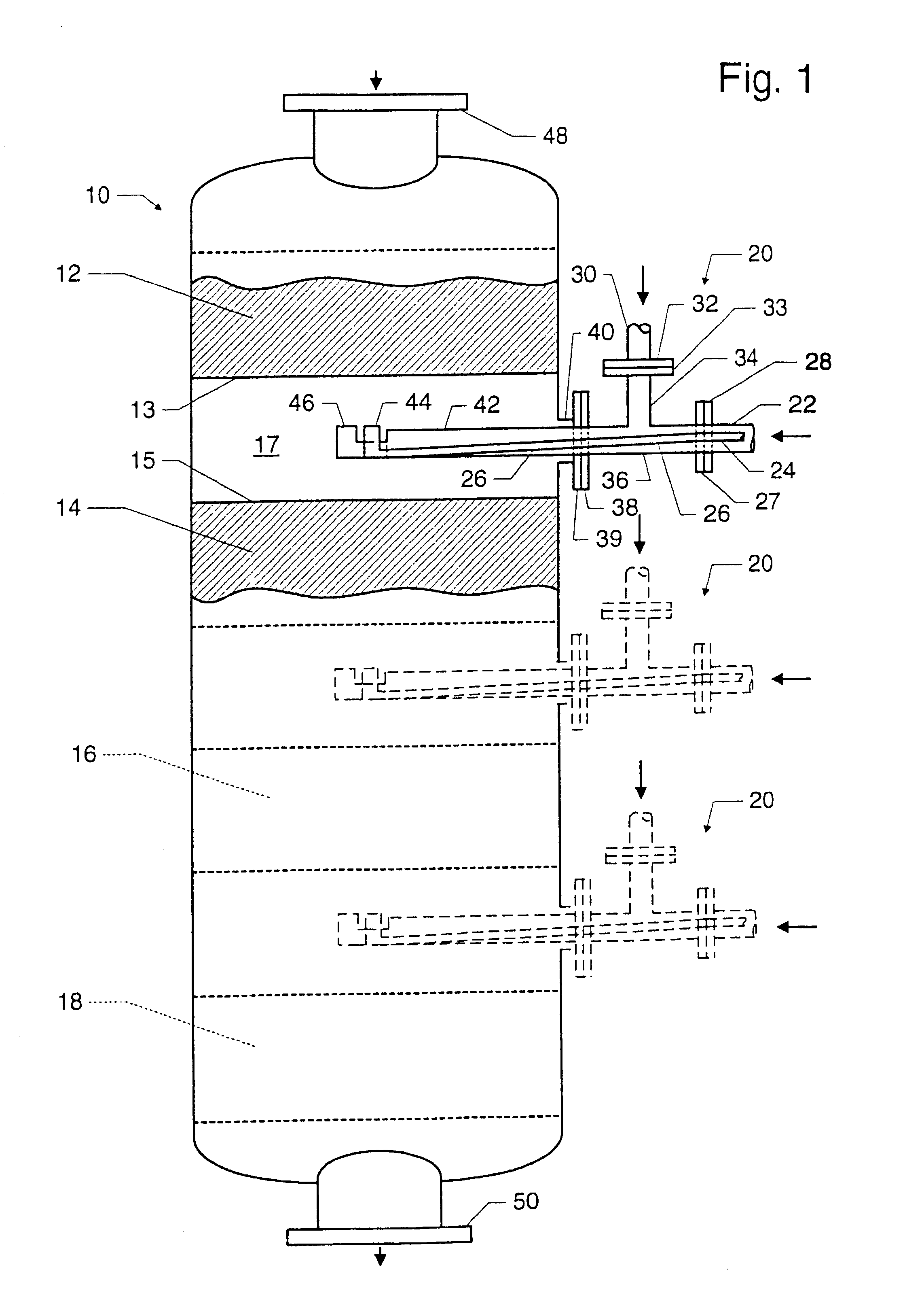
[0036]Referring to FIGS. 1–8, nozzle 46 has a design flow rate of 100 flow units, nozzle 44 has a design flow rate of 70 flow units, and the initial need for quench material flow rate between beds 12 and 14 is 100 flow units. Thus, valve 106 is open completely and valve 110 is completely closed. Over time, the need for quench flow decreases, because the catalyst in bed 12 deactivates due to nitrogen poisoning. The symptom of deactivation in bed 12 is the temperature in bed 14, which decreases over time while the flow rate of quench material through nozzle 46 is constant. When bed 14 temperatures falls to an unacceptable extent, valve 106 is closed slightly. This decreases the flow or quench material and thereby allows the temperatures in bed 14 to increase to the desired temperature for bed 14.

[0037]Over time, valve 106 continues to be closed to a greater and greater extent in response to more severe deactivation of the catalyst in bed 12. After a period of time, valve 106 is closed...

example 2

[0040]Example 2 illustrates the apparatus and method of this invention providing quench material to chamber 10 over a similar period of time as that covered in Example 1. However, the focus of this Example 2 is on providing quench between beds 16 and 18, rather than between beds 12 and 14 as in Example 1. All references to valves, nozzles, and quench flows in this Example 2 are thus to those for the assembly 20 between beds 16 and 18, rather than to those associated with the assembly 20 between beds 12 and 14 in the case of Example 1.

[0041]Referring then to the assembly 20 between beds 16 and 18, nozzle 46 has a design flow rate of 100 flow units and nozzle 44 has a design flow rate of 70 flow units. For purposes of this illustration, it is assumed that, for each of nozzles 44 and 46, 70% of the design flow rate of the nozzle is the point at which the quenching performance of the nozzle becomes so inefficient as to be unacceptable. The initial need for quench material flow between b...

example 3

[0046]Example 3 illustrates another embodiment of this invention where the manual valves 106 and 110 shown in FIG. 2 are replaced with flow regulating or control valves. As used herein, a flow regulating valve is a valve in which the extent of opening of the valve is automatically controlled by a pneumatic or electrical signal from a control station, which is usually located in a centralized control facility, such as a control room or control building. Compared to a manual valve, the position of which is adjusted by hand turning or manipulation of a handle on the valve itself, the position of a regulating valve can be controlled more precisely and more frequently. With a regulating or control valve, accurate and frequent adjustments to the valve position are possible to an extent that would be excessively time-consuming or tedious for an operator to attempt by hand turning of a manual valve. Consequently, a flow regulating valve permits flow rates to be continually optimized in resp...


PUM


Abstract

An apparatus and method for contacting fluids in a fluid-solids contacting chamber is disclosed. The fluid-solid contacting chamber has a plurality of beds, and the chamber comprises a plurality of conduits and outlet ports that are capable of providing improved fluid distribution of fluids that are introduced above or between the beds. One or more conduits are arranged within a single conduit, which provides a compact and inexpensive assembly for conveying the fluids to each conduit's outlet port. In operation, the fluid flow to the outlet port of each conduit is regulated within that outlet port's most efficient operating range, and since the flows can regulated simply by hand, the method of this invention can be practiced readily. Catalytic condensation and other hydrocarbon process units that employ this invention will have increased on-stream efficiencies and realize significant economic benefits.

Description

CROSS-REFERENCE TO RELATED APPLICATION[0001]This application is a Division of U.S. application Ser. No. 09 / 505,325 filed Feb. 16, 2000, now U.S. Pat. No. 6,455,015 the entire contents of which are hereby incorporated by reference.FIELD OF THE INVENTION[0002]This invention relates to an apparatus for contacting fluids in a fluid-solids contacting zone such as an adsorption zone or a reaction zone. More particularly, the invention is directed to the contacting of two fluids comprising a liquid phase and a vapor phase in a fluid-solids contacting zone, and to means and methods for effecting improved heat exchange between the vapor and liquid phases in the contacting vessel. More specifically, the invention relates to a new and improved method and apparatus for uniformly distributing a liquid phase into a flowing liquid, vapor, or mixed liquid-vapor phase in a granular or particulate solids contacting zone, as in an adsorption tower or in a catalytic reactor such as a catalytic condensa...

Claims


Application Information

Patent Timeline
IPC IPC(8): C10G59/00B01D53/04B01J8/04B01J19/26
CPCB01D53/0446B01J8/0453B01J8/0492B01J19/26B01J8/0496B01D53/0431B01D2259/404B01J2219/1943B01J2208/00362B01J2208/00548B01J2219/00119B01J2219/185
Inventor KILROY, JAMES W.
Owner UOP LLC