Very narrow band, two chamber, high reprate gas discharge laser system
What is Al technical title?
Al technical title is built by PatSnap Al team. It summarizes the technical point description of the patent document.
a laser system and gas discharge technology, applied in the field of very narrow band, two chambers, high-reprate gas discharge laser systems, can solve the problems of adversely affecting wavelength and/or bandwidth, and affecting the quality of laser beams. the effect of wavelength stability and bandwidth, the quality of beam quality specifications for pulse energy stability, and the tightening of output power
Inactive Publication Date: 2006-01-10
CYMER INC
View PDF41 Cites 29 Cited by
Summary
Abstract
Description
Claims
Application Information
AI Technical Summary
This helps you quickly interpret patents by identifying the three key elements:
Problems solved by technology
Method used
Benefits of technology
Problems solved by technology
These excimer lasers, when used for integrated circuit lithography, are typically operated in an integrated circuit fabrication line “around-the-clock” producing many thousands of valuable integrated circuits per hour; therefore, down-time can be very expensive.
Some improvements can be provided with the basic design as described in the '884 patent; however, major improvements with that basic design may not be feasible.
For example, with a single discharge chamber precise control of pulse energy may adversely affect wavelength and / or bandwidth and vice versa especially at very high pulse repetition rates.
Laser systems comprised of two separate systems tend to be substantially more expensive, larger and more complicated than comparable single chamber laser systems.
Therefore, commercial application of these two chamber laser systems has been limited.
Method used
Image
Click on the blue label to locate the original text in one second.
Reading with bidirectional positioning of images and text.
Examples
first preferred embodiment
Three Wavelength Platform
First General Layout
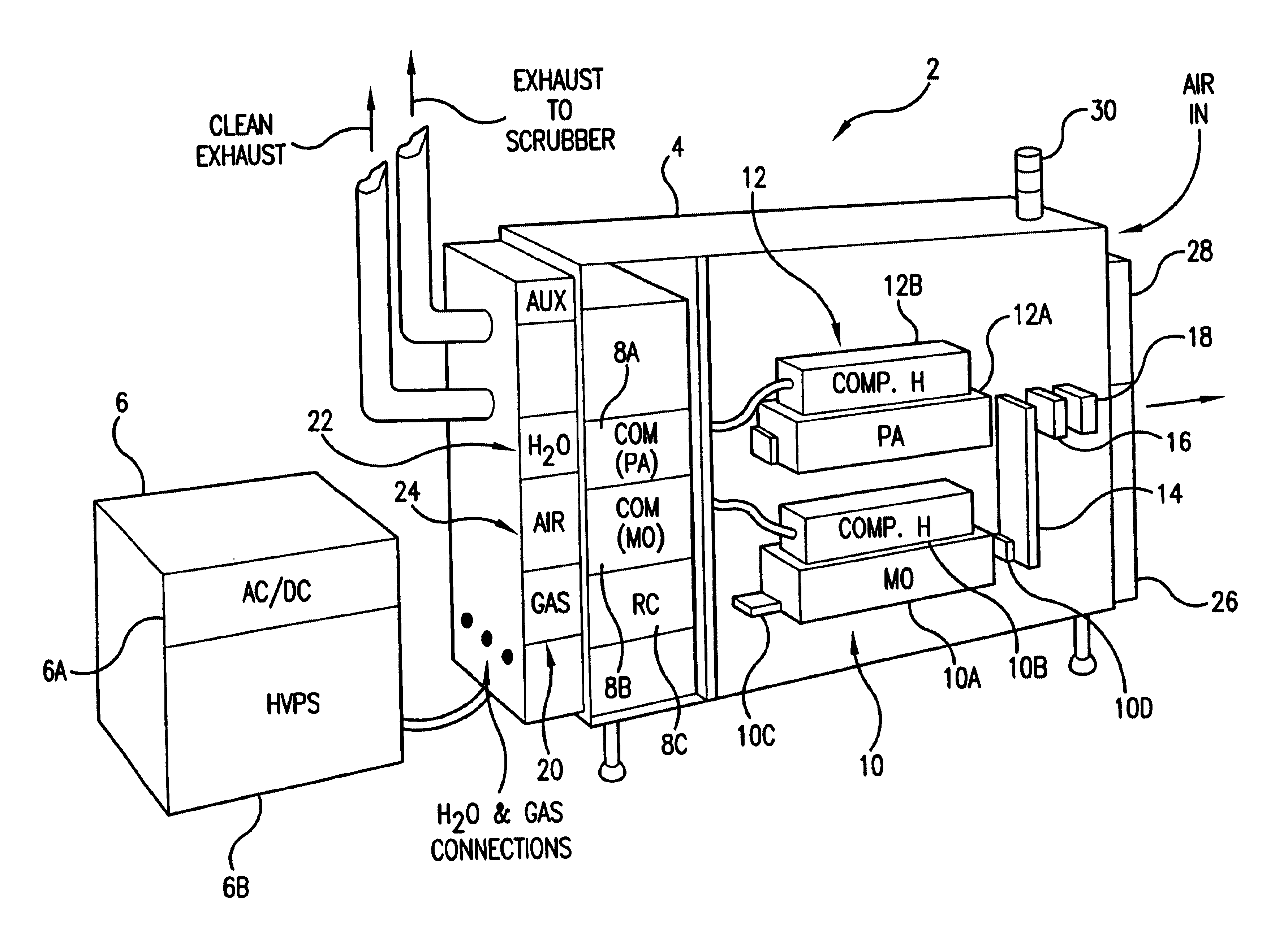
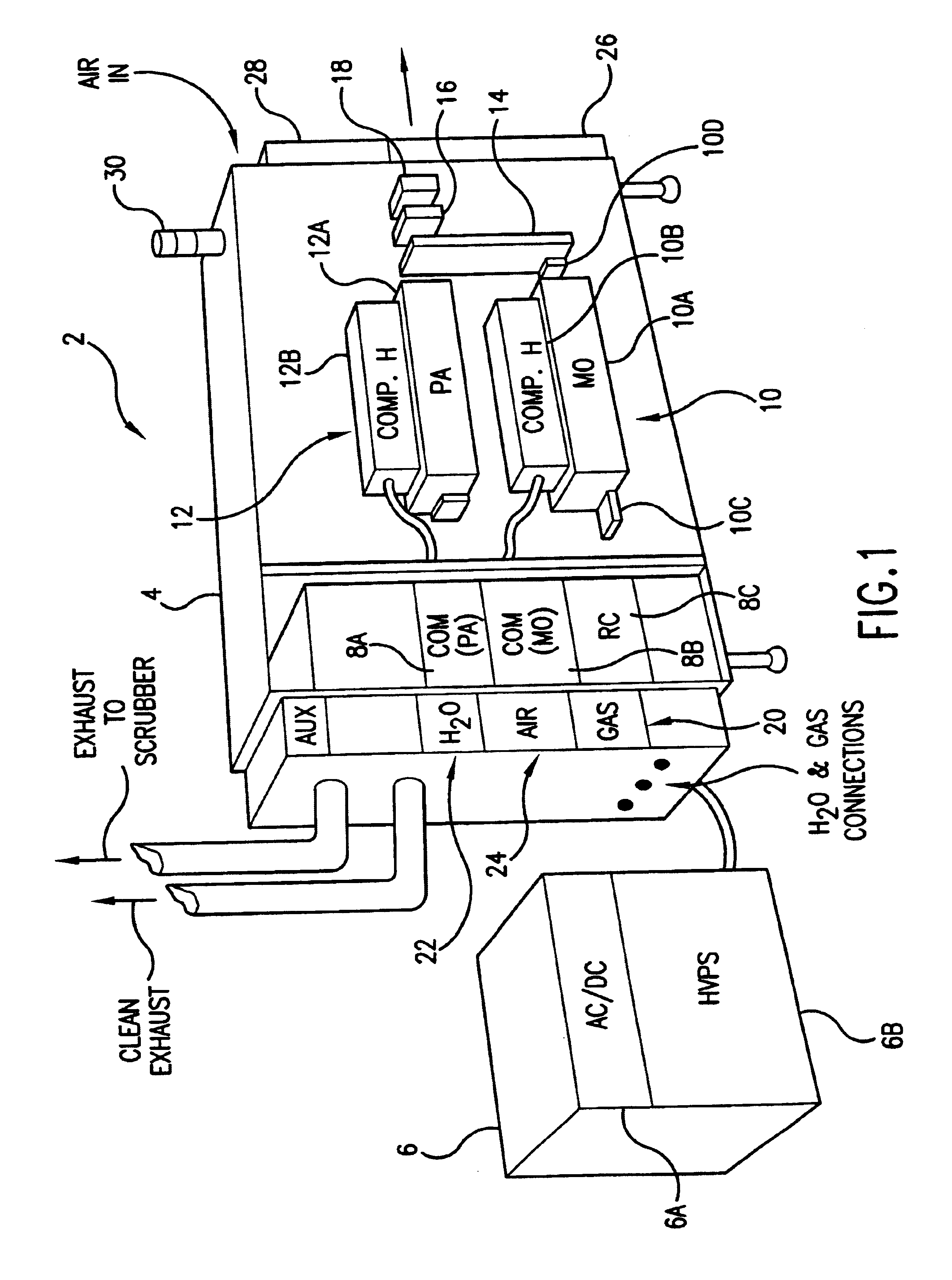
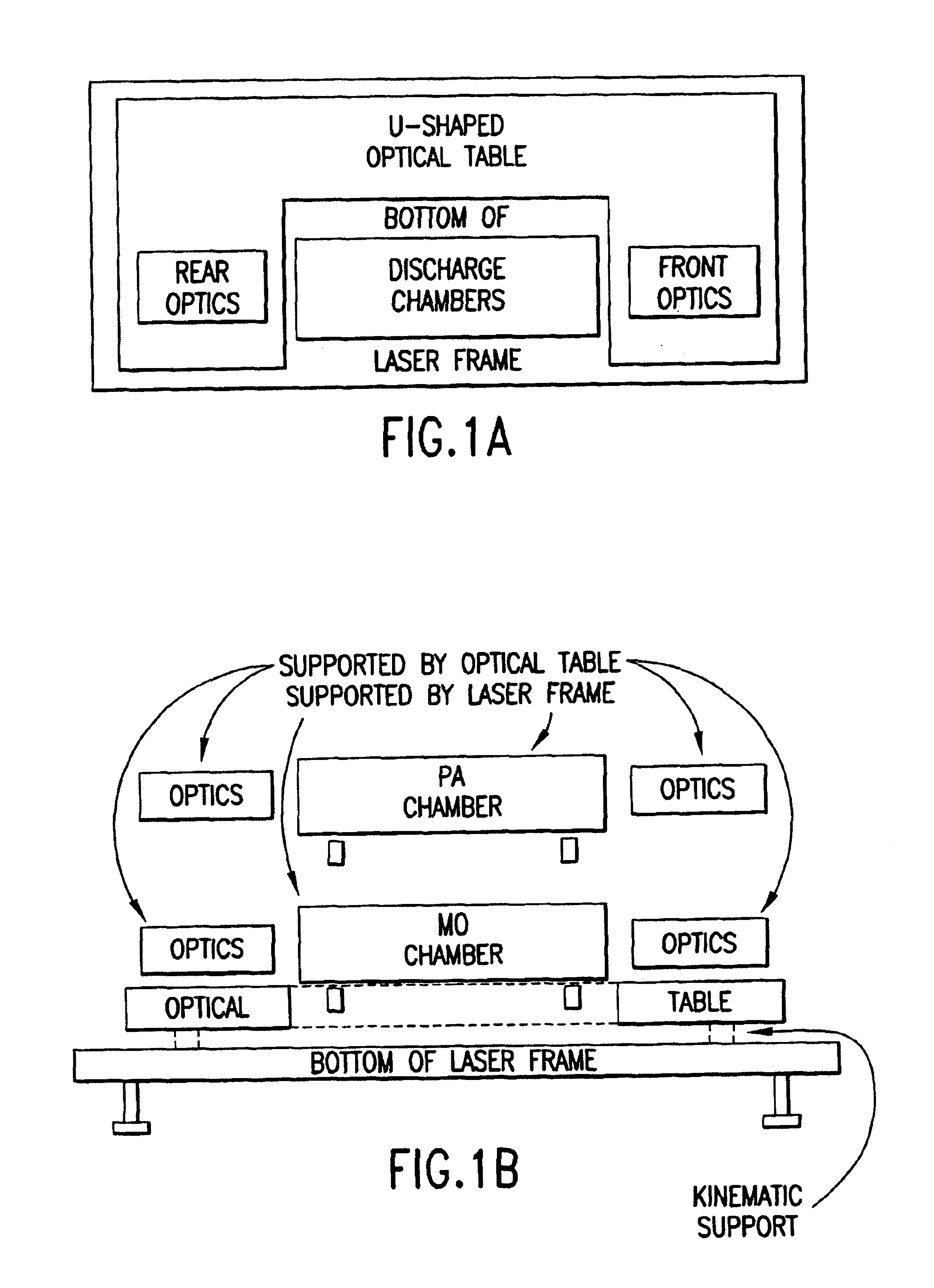
[0044]FIG. 1 is a perspective view of a first preferred embodiment of the present invention. This embodiment is an injection seeded narrow band excimer laser system configured as a MOPA laser system. It is specially designed for use as a light source for integrated circuit lithography. The major improvement in the present invention as exemplified in this embodiment over the prior art lithography lasers is the utilization of injection seeding and in particular a master oscillator-power amplifier (MOPA) configuration with two separate discharge chambers.
[0045]This first preferred embodiment is an argon-fluoride (ArF) excimer laser system; however, the system utilizes a modular platform configuration which is designed to accommodate either krypton-fluoride (KrF), ArF or fluorine (F2) laser components. This platform design permits use of the same basic cabinet and many of the laser system modules and components for either of these three types...
PUM
Property
Measurement
Unit
voltages
aaaaa
aaaaa
charging voltage
aaaaa
aaaaa
voltage electrical potential
aaaaa
aaaaa
Abstract
An injection seeded modular gas discharge laser system capable of producing high quality pulsed laser beams at pulse rates of about 4,000 Hz or greater and at pulse energies of about 5 mJ or greater. Two separate discharge chambers are provided, one of which is a part of a master oscillator producing a very narrow band seed beam which is amplified in the second discharge chamber. The chambers can be controlled separately permitting separate optimization of wavelength parameters in the master oscillator and optimization of pulse energy parameters in the amplifying chamber. A preferred embodiment in an ArF excimer laser system configured as a MOPA and specifically designed for use as a light source for integrated circuit lithography. In the preferred MOPA embodiment, each chamber comprises a single tangential fan providing sufficient gas flow to permit operation at pulse rates of 4000 Hz or greater by clearing debris from the discharge region in less time than the approximately 0.25 milliseconds between pulses. The master oscillator is equipped with a line narrowing package having a very fast tuning mirror capable of controlling centerline wavelength on a pulse-to-pulse basis at repetition rates of 4000 Hz or greater to a precision of less than 0.2 pm.
Description
[0001]This application is a continuation of U.S. Ser. No. 10 / 012,002 filed Nov. 30, 2001, now U.S. Pat. No. 6,625,191 which is a continuation-in-part of U.S. Ser. No. 10 / 006,913 filed Nov. 29, 2001, which issued on Mar. 18, 2003 as U.S. Pat. No. 6,535,531, Ser. No. 09 / 943,343 filed Aug. 29, 2001, which issued on May 20, 2003 as U.S. Pat. No. 6,567,450, Ser. No. 09 / 854,097, filed May 11, 2001 now U.S. Pat. No. 6,757,316, Ser. No. 09 / 848,043 filed May 3, 2001, which issued on Apr. 15, 2003 as U.S. Pat. No. 6,549,551, Ser. No. 09 / 459,165 filed Dec. 10, 1999, which issued on Apr. 9, 2002 as U.S. Pat. No. 6,370,174, Ser. No. 09 / 794,782 filed Feb. 27, 2001, which issued on Mar. 11, 2003 as U.S. Pat. No. 6,532,247, Ser. No. 09 / 771,789, filed Jan. 29, 2001 which issued on Mar. 25, 2003 as U.S. Pat. No. 6,539,042, Ser. No. 09 / 768,753, filed Jan. 23, 2001 which issued on Jul. 2, 2002 as U.S. Pat. No. 6,414,979, Ser. No. 09 / 684,629 filed Oct. 6, 2000, which issued on Aug. 27, 2002 as U.S. Pat....
Claims
Application Information
Patent Timeline
Application Date:The date an application was filed.
Publication Date:The date a patent or application was officially published.
First Publication Date:The earliest publication date of a patent with the same application number.
Issue Date:Publication date of the patent grant document.
PCT Entry Date:The Entry date of PCT National Phase.
Estimated Expiry Date:The statutory expiry date of a patent right according to the Patent Law, and it is the longest term of protection that the patent right can achieve without the termination of the patent right due to other reasons(Term extension factor has been taken into account ).
Invalid Date:Actual expiry date is based on effective date or publication date of legal transaction data of invalid patent.
Inventor KNOWLES, DAVID S.BROWN, DANIEL J. W.BESAUCELE, HERVE A.MEYERS, DAVID W.ERSHOV, ALEXANDER I.PARTLO, WILLIAM N.SANDSTROM, RICHARD L.DAS, PALASH P.ANDERSON, STUART L.FOMENKOV, IGOR V.UJAZDOWSKI, RICHARD C.ONKELS, ECKEHARD D.NESS, RICHARD M.SMITH, SCOTT T.HULBURD, WILLIAM G.OICLES, JEFFREY