Tube for the electrostatic coating of workpieces

Active Publication Date: 2006-01-17
DURR SYST INC
View PDF64 Cites 10 Cited by
  • Summary
  • Abstract
  • Description
  • Claims
  • Application Information

AI Technical Summary

Benefits of technology

[0016]The tube according to the invention can be produced simply and at low expense, particularly through extrusion, wherein

Problems solved by technology

Due to these requirements, specially suited plastics must be used, which, however, have the disadvantage that these plastics do not also have optimum electrical insulating properties.
Therefore, in a coating system of the mentioned class, if piggable tubes for media at a high voltage are to be laid close to grounded parts of the system or can accidentally come close to grounded parts, then the problem arises of the risk of voltage breakdown or at least undesirably high leakage currents.
Cons

Method used


Image

  • Tube for the electrostatic coating of workpieces
  • Tube for the electrostatic coating of workpieces

Examples


Embodiment Construction

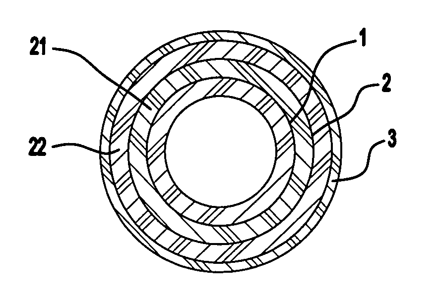
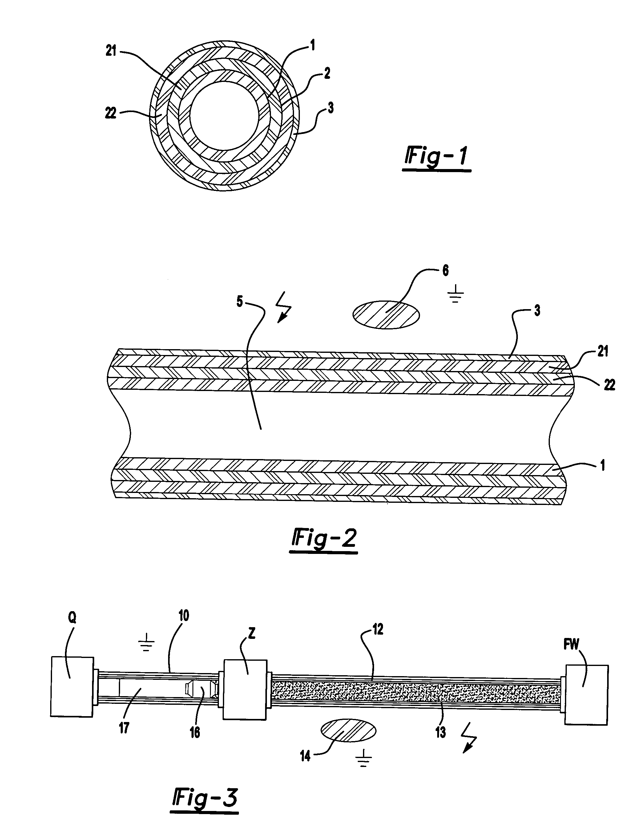
[0021]The cylindrical tube illustrated in FIG. 1 consists of the piggable inner layer 1, which borders a high-voltage-resistant intermediate layer 2 acting as an isolating layer with no gaps. This intermediate layer is surrounded by a protective outer layer 3 also as much as possible without gaps. The intermediate layer 2 can be formed with multiple layers and for the illustrated example consists of two partial layers 21 and 22 bordering each other without gaps. The entire tube is electrically non-conductive.

[0022]For the inner layer 1, a plastic is selected, which guarantees as much as possible the desired properties of a good piggable tube mentioned in the introduction. Well suited is, e.g., PFA (perfluoroalkoxy polymers), for example PFA 420.

[0023]The intermediate layer 2 consists of another material than the piggable inner layer 1. To achieve the high-voltage isolation function, the tubes can be manufactured, e.g., from PE (polyethylene), particularly LDPE (low-density PE). If p...


PUM


Abstract

For the pig delivery of the coating material at high voltage in a system for electrostatic mass-production coating of workpieces in the vicinity of grounded parts of the system, a multi-layer tube is provided, whose innermost layer forms the piggable inner wall, while a second layer consists of a high-voltage-resistant isolation material and is surrounded by a protective outer layer.

Description

PRIOR APPLICATIONS[0001]This application claims priority to German Patent Application No. DE 102 39 516.0 filed on Aug. 28, 2002.BACKGROUND OF THE INVENTION[0002]The invention concerns a piggable tube and a method for producing such a tube according to the preamble of the independent claims. More specifically, it deals with a tube, which can be used to deliver electrically conductive coating material by means of a pig into the vicinity of parts of the system that are grounded or set to a low voltage in a system for mass-production coating of workpieces.[0003]As is known, such tubes are needed in coating systems for the electrostatic mass-production coating of workpieces, such as vehicle chassis, with water enamel or other conductive coating material, which can be set to a high voltage on the order of 100 kV. The coating material is moved through the tube by the pig, with the pig also having to act as a perfect separating body between its own liquid or gaseous pushing medium and the ...

Claims


Application Information

Patent Timeline
IPC IPC(8): F16L55/16B05B5/16B05B12/14F16L11/12
CPCB05B5/1608B05B12/1481F16L11/12B05B5/1616Y10T428/1393B05B12/14
Inventor MARTIN, HERBERTSTIEGLER, MARTIN
Owner DURR SYST INC
Why Eureka
Try Eureka