Method and device for the surface machining of workpieces composed of non-brittle materials in optical lens manufacturing and tool for this purpose

a technology of optical lens and workpiece, which is applied in the direction of shaping cutters, manufacturing tools, instruments, etc., can solve the problems of not being able to follow on with any fining process using fixed-shape tools, not being able to cut blank material more than 5 mm thick, and known rotational machining methods using relatively expensive devices. , to achieve the effect of convenient chip removal and device loading

Inactive Publication Date: 2006-01-31
SATISLOH GMBH
View PDF26 Cites 18 Cited by
  • Summary
  • Abstract
  • Description
  • Claims
  • Application Information

AI Technical Summary

Benefits of technology

[0021]Finally, both the work spindle and the tool spindle may be aligned horizontally. This arrangement is preferred, because it facilitates loading of the device and chip removal during the machining. Also feas...

Problems solved by technology

With these surface forms, it is in fact not possible to follow on with any fining processes that use fixed-shape tools.
The moving parts in this must be of extremely lightweight construction, especially since the high accelerations place great technical demands on the linear motors, the measuring systems and not l...

Method used


Image

  • Method and device for the surface machining of workpieces composed of non-brittle materials in optical lens manufacturing and tool for this purpose
  • Method and device for the surface machining of workpieces composed of non-brittle materials in optical lens manufacturing and tool for this purpose
  • Method and device for the surface machining of workpieces composed of non-brittle materials in optical lens manufacturing and tool for this purpose

Examples


Embodiment Construction

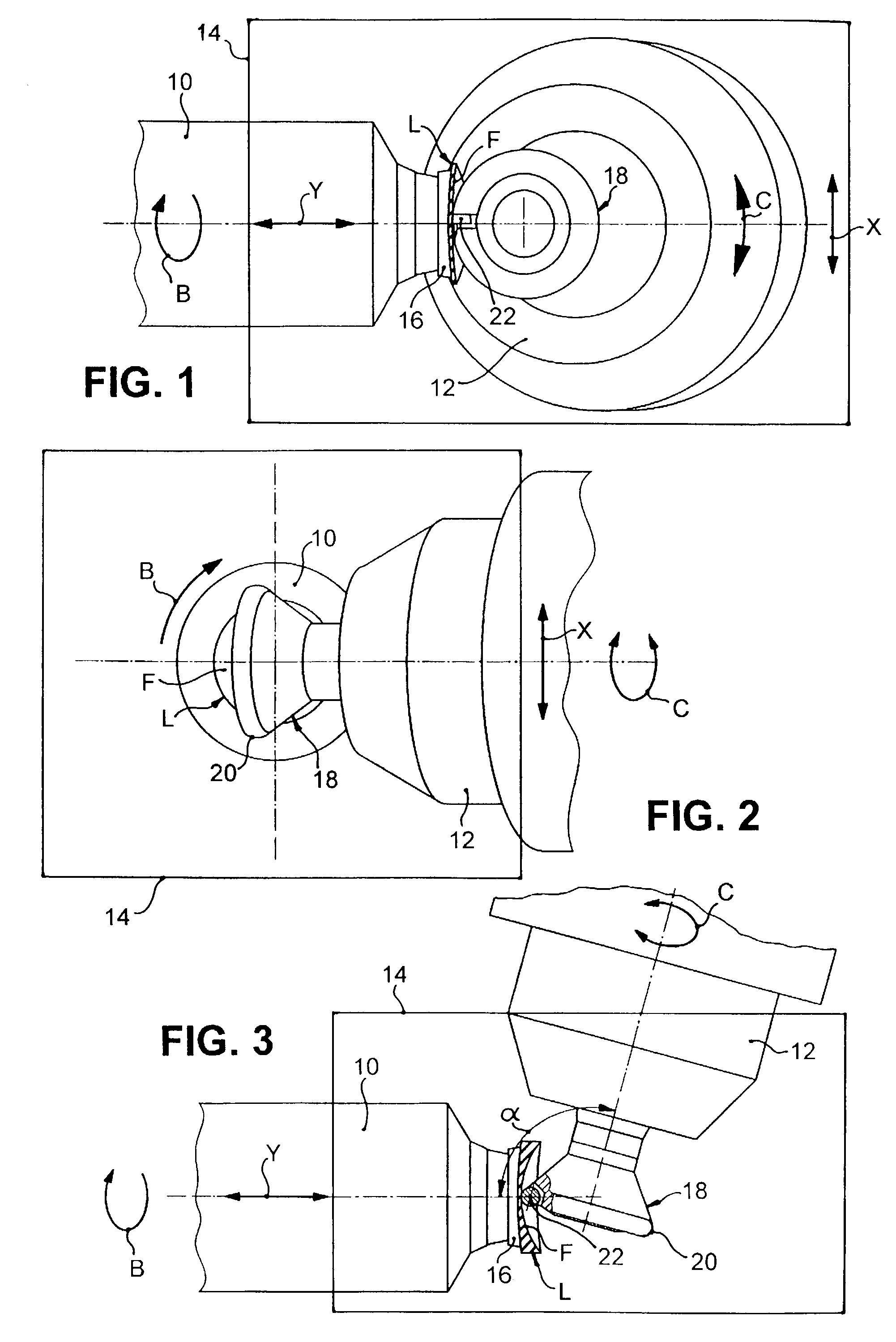
[0031]For the sake of simplicity, in FIGS. 1 to 3 only the work spindle 10 and the tool spindle 12 of the device for surface machining of plastic spectacle lenses L are represented, these spindles extending, suitably sealed off, into a working space 14 that can be shielded from the surroundings and is indicated by the solid lines of a rectangle. For machining of the prescription surface F, the spectacle lens L, blocked on a blocking piece 16, is mounted on the end of the work spindle 10 in a manner known in the art, in such a way that it can rotate coaxially with the work spindle 10. For this purpose the work spindle 10 can be driven to rotate about the axis of work rotation B, with the speed and the angle of rotation controlled by CNC, by means of an electric motor (not shown). Furthermore, the work spindle 10 can be adjusted, positionally controlled by CNC, by means of a carriage (likewise not shown) and assigned drive and control elements, in the linear axis Y, which in the examp...


PUM

PropertyMeasurementUnit
Areaaaaaaaaaaa
Circumferenceaaaaaaaaaa

Abstract

A device is disclosed for the surface machining of, among other things, plastic spectacle lenses, which has a work spindle, by means of which the spectacle lens can be driven with a controlled angle of rotation about an axis of work rotation, and a tool spindle, by means of which a tool can be driven to rotate about an axis of tool rotation, work and tool spindle being movable relative to one another with their positions controlled in two axes running at right angles. For rotational machining of the surface of the spectacle lens to be machined, the tool can also be swiveled by means of the tool spindle with a controlled angle of rotation about the axis of tool rotation, so that a rotational cutting edge provided on the tool can be brought into a defined rotational machining engagement with the surface of the spectacle lens to be machined as a function of the angle of rotation of the spectacle lens. Also included is a combined milling and rotational machining tool and a combined milling and rotational machining method. As a result, high cutting rates and very good surface qualities can be easily and efficiently achieved in the surface machining.

Description

BACKGROUND OF THE INVENTION[0001]The present invention relates to a method and a device for the surface machining of workpieces composed of non-brittle materials in optical lens manufacturing, and to a tool for this purpose. The invention relates in particular to the industrial machining of prescription surfaces of spectacle lenses composed of plastics such as polycarbonate, CR39 and so-called “high index” materials.[0002]This machining is usually performed on an injection molded plastic spectacle lens “blank”, which has a standardised, finished convex outer surface with, for example, a spherical or progressive shape. Machining gives the generally concave inner or prescription surfaces a spherical, aspherical, toroidal, atoroidal, progressive or freeform geometry, depending on the desired optical effect. After blocking the spectacle lens blank with its outer surface on a blocking piece, the typical, conventional sequence in machining of the inner surface provides for a milling or ro...

Claims


Application Information

Patent Timeline
IPC IPC(8): B24B13/00B23C3/16B23C3/02B23C5/00B23C5/22B23C5/28B24B13/01B24B13/04B24B13/06
CPCB23C3/023B23C5/006B23C5/2273B24B13/01B24B13/043B24B13/06B23B2226/31B23C2200/203Y10T407/1946B23C2226/61B23C2226/315B29D11/00932
Inventor DIEHL, JOACHIMLAUTZ, RONALDTROSS, KARL-HEINZ
Owner SATISLOH GMBH
Why Eureka
Try Eureka