Film bulk acoustic resonator and method of forming the same

a resonator and film technology, applied in piezoelectric/electrostrictive/magnetostrictive devices, piezoelectric/electrostriction/magnetostriction machines, impedence networks, etc., can solve the problem of reducing manufacturing costs, unable to integrate the conventional resonator and filter in the frequency band of more than 1 ghz, and the insertion loss is still greater than the conventional resonator, so as to achieve high reflective characteristi

Inactive Publication Date: 2006-01-31
SAMSUNG ELECTRO MECHANICS CO LTD
View PDF9 Cites 35 Cited by
  • Summary
  • Abstract
  • Description
  • Claims
  • Application Information

AI Technical Summary

Benefits of technology

[0022]In order to overcome the above and other problems, it is an object to provide a FBAR having a high reflective characteristic and a lower insertion loss and to prevent signals generated in a resonator area from being transmitted to a substrate.

Problems solved by technology

However, the super high frequency band component is difficult in minimizing in size and lowering a manufacturing cost.
For example, a conventional dielectric resonator and filter used in the frequency band of more than 1 GHz cannot be integrated into the minimized and multi-functional mobile communication terminal due to the bulky size and shape of the conventional resonator and filter.
Although an acoustic surface resonator or crystal resonator replacing a dielectric resonator has been introduced, an insertion loss is still greater than the conventional resonator, and it is impossible to integrate and minimize the acoustic surface resonator in a desired size and volume.
Accordingly, a manufacturing process becomes complicated, and the manufacturing cost is increased.
In addition, the SMR is lower than the air gap method in reflective characteristics and limited in being implemented as a resonator due to a decreased effective bandwidth.
As a result, characteristics of the conventional FBAR deteriorate when the FBAR is implemented in an integrated circuit operating in the high frequency band.
As a result, the number of the vie holes H is increased, the via holes H formed on a specific position of the FBAR badly effects the characteristics of the FBAR.
Although an undercut of the FBAR may be prevented in a conventional sacrificing layer forming process using an dry etching operation of the photo resist after a wet etching operation of the sacrificing layer, this process is very complicated, and the undercut is not easily controlled.
If a wing tip is generated due to a lower side profile angle of the photo resist during the above process, the structure of the FBAR becomes weak and easily deformed.
In addition to the above problems, the resonator frequency is not easily controlled in the above conventional FBAR.

Method used


Image

  • Film bulk acoustic resonator and method of forming the same
  • Film bulk acoustic resonator and method of forming the same
  • Film bulk acoustic resonator and method of forming the same

Examples


Embodiment Construction

[0043]Reference will now be made in detail to the embodiments of the present invention, examples of which are illustrated in the accompanying drawings, wherein like reference numerals refer to the like elements throughout. The embodiments are described below in order to explain the present invention by referring to the figures.

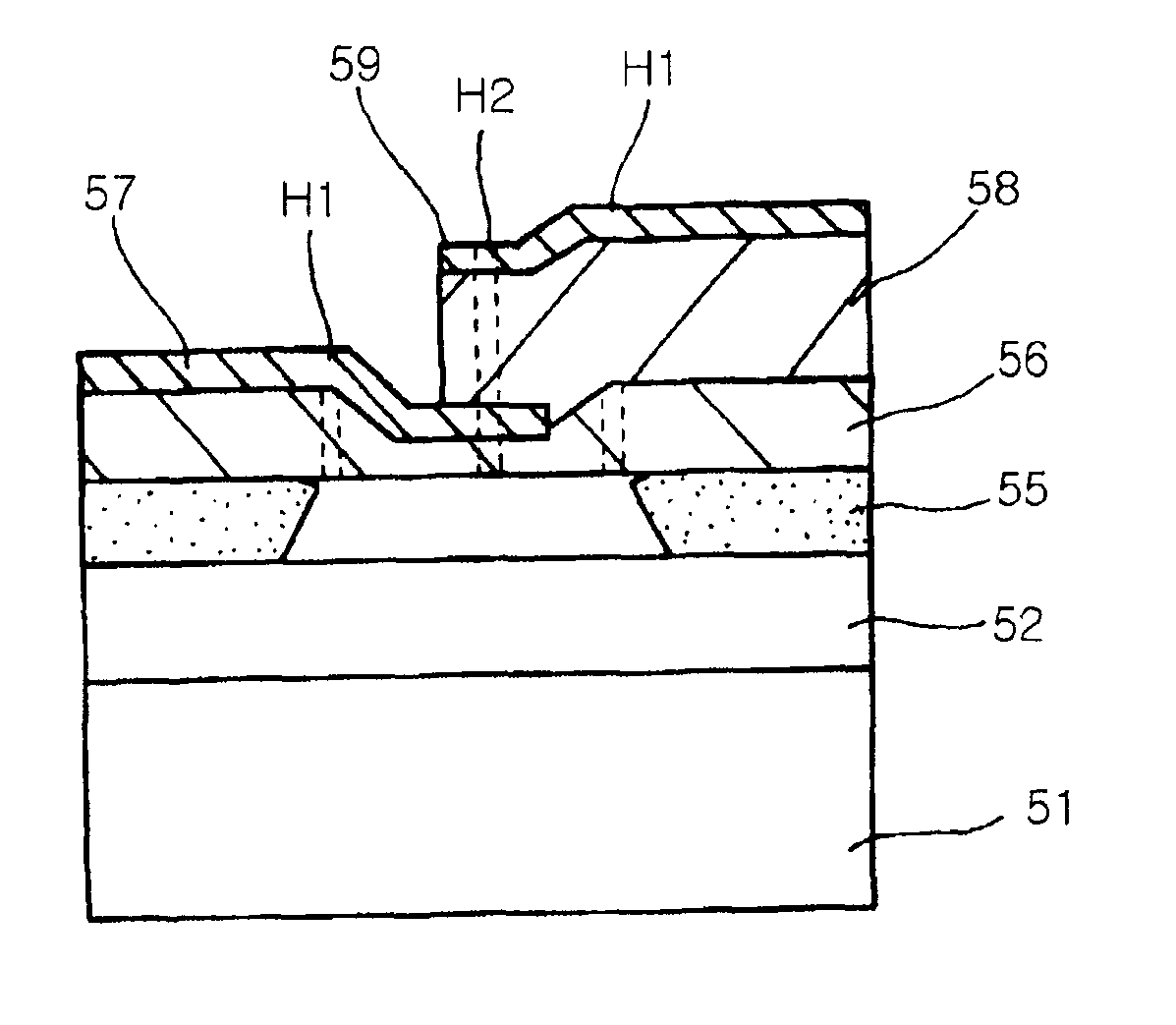
[0044]FIGS. 4A and 4B are a cross-sectional view and a plan view of a FBAR according to an embodiment of the present invention, respectively. Referring to FIG. 4A, the FBAR includes a substrate 51, an insulation layer 52 formed on the substrate 51, a membrane supporting layer 55 formed on the insulation layer 52 to have an air gap A3, a membrane layer 56 formed on the membrane supporting layer 55, a first electrode 57 formed on the membrane layer 56, a piezoelectric layer 58 formed on the first electrode 57, and a second electrode 59 formed on the piezoelectric layer 58.

[0045]According to this embodiment of the present invention, an insertion loss is reduced b...


PUM


Abstract

A film bulk acoustic resonator (FBAR) includes an insulation layer on a substrate to prevent a signal from being transmitted to a substrate. The FBAR includes a portion of a membrane layer corresponding to an activation area to adjust a resonance frequency band and improve a transmission gain of the resonance frequency band, the portion of the membrane layer being partially etched to have a thickness less than the other portion of the membrane layer. A method of forming the FBAR includes forming an sacrificing layer made of polysilicon, forming an air gap using a dry etching process, and forming a via hole. The method prevents structural problems occurred in a conventional air gap forming process and provides locations and the number of the via holes to be controlled.

Description

CROSS-REFERENCE TO RELATED APPLICATIONS[0001]This application claims the benefit of Korean Application No. 10-2002-19825, filed Apr. 11, 2002, in the Korean Intellectual Property Office, the disclosure of which is incorporated herein by reference.BACKGROUND OF THE INVENTION[0002]1. Field of the Invention[0003]The present invention relates to a film bulk acoustic resonator and a method of manufacturing the same, and more particularly, to a film bulk acoustic resonator and a method of forming the same having a thermal oxidation layer and a stable resonating structure easily formed by a dry etching process.[0004]2. Description of the Related Art[0005]Recently, components, such as a radio frequency related component, used in a mobile communication terminal have been rapidly improved according to a tendency toward minimization and multi-function of the mobile communication terminal. A filter, one of critical components in the mobile communication terminal, performs a function of filterin...

Claims


Application Information

Patent Timeline
Patent Type & Authority Patents(United States)
IPC IPC(8): H01L41/08H03H9/02H01L41/187H01L41/09H01L41/22H03H3/02H03H3/04H03H9/15H03H9/17
CPCH03H3/04H03H9/173H03H2003/0442H03H2003/021H03H9/15
Inventor JANG, JAE WOOKSUNWOO, KUK HYUN
Owner SAMSUNG ELECTRO MECHANICS CO LTD
Why Eureka
Try Eureka