Method for mid load operation of auto-ignition combustion

a technology of auto-ignition combustion and mid-load operation, which is applied in the direction of machines/engines, output power, electric control, etc., can solve the problems of difficult control of auto-ignition at part load, low residual content, and limit at which an engine can be operated with a diluted mixture, so as to achieve the effect of increasing the limit of mid-load operation

Active Publication Date: 2006-02-07
GM GLOBAL TECH OPERATIONS LLC
View PDF9 Cites 82 Cited by
  • Summary
  • Abstract
  • Description
  • Claims
  • Application Information

AI Technical Summary

Problems solved by technology

There is, however, a limit at which an engine can be operated with a diluted mixture because of misfire and combustion instability as a result of a slow burn.
In four-stroke engines with traditional valve means, the residual content is low, and controlled auto-ignition at part load is difficult to achieve.
In all the above methods, the range of engine speeds and loads in which controlled auto-ignition combustion can be achieved is relatively narrow.
In general, the engine operation is limited by combustion stability at low load and by in-cylinder pressure rise or amplitude of pressure oscillation at high load.
Too large a pressure rise or amplitude of pressure oscillation results in a combustion-generated noise called knocking.
There is concern about an increase in Nitric Oxides (NOx) emissions due to spark ignition combustion that may require an expensive lean NOx after-treatment device for emission control.

Method used


Image

  • Method for mid load operation of auto-ignition combustion
  • Method for mid load operation of auto-ignition combustion
  • Method for mid load operation of auto-ignition combustion

Examples


Embodiment Construction

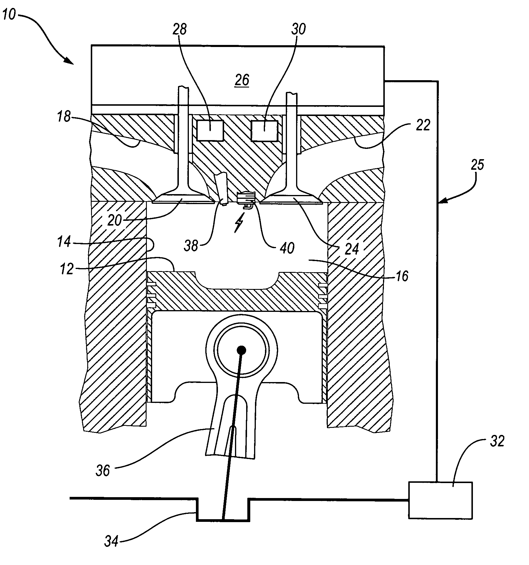
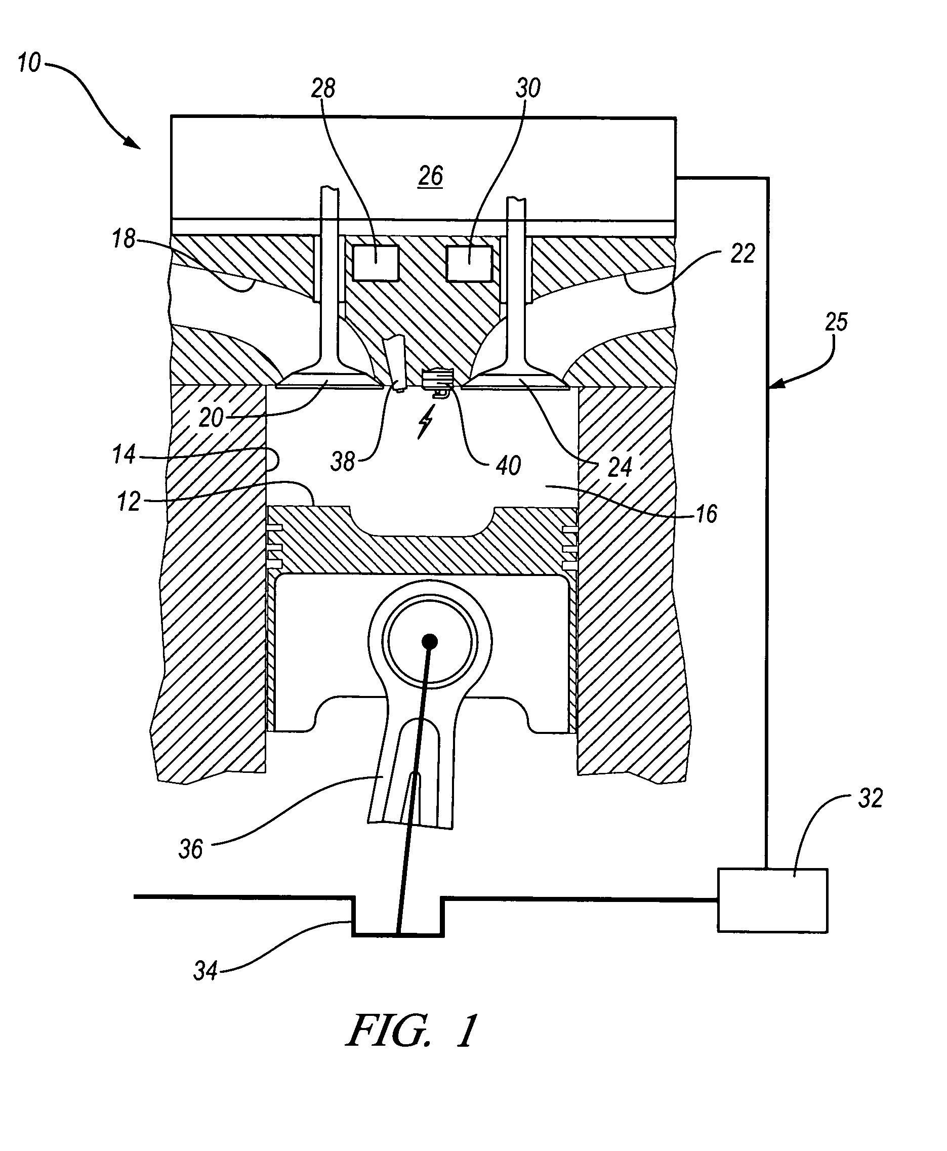
[0041]In general, the present invention teaches a method for expanding the mid load operation limit in a four-stroke gasoline direct-injection controlled auto-ignition combustion engine. A system is employed for variably actuating the intake and exhaust valves and for operating the valves with either an exhaust re-compression or an exhaust re-breathing valve strategy. A spark plug is provided and a fuel injector having multiple injection capability is employed. Early in the intake stroke, a first fuel charge is injected into the combustion chamber to form a lean air-fuel mixture in the chamber. Later in the intake stroke, a second fuel charge is injected into the combustion chamber to form a stratified ignitable air-fuel mixture concentrated near the spark plug. The overall mixture is maintained stoichiometric so a traditional three-way after treatment device may be used for exhaust emission control. At a controlled timing before top dead center of the compression stroke, the ignita...


PUM


Abstract

A method is disclosed for expanding the mid load operation limit in a four-stroke gasoline direct-injection controlled auto-ignition combustion engine. A system is employed for variably actuating the intake and exhaust valves and for operating the valves with an exhaust re-compression or exhaust re-breathing valve strategy. A spark plug is provided. A fuel injector having multiple injection capability is employed. A first fuel charge is injected into the combustion chamber to form a lean air-fuel mixture. A second fuel charge is injected into the combustion chamber to form a stratified air-fuel mixture having an ignitable mixture located near the spark plug. The ignitable mixture is ignited at the spark gap, thereby causing spark-ignition combustion that causes a sufficient increase in chamber pressure and temperature to trigger auto-ignition of the lean air-fuel mixture, resulting in the obtaining of a higher engine load before a pressure rise rate in the combustion chamber exceeds a prescribed threshold value.

Description

CROSS-REFERENCE TO RELATED APPLICATIONS[0001]This application claims priority from U.S. Provisional Patent Application No. 60 / 587,104 filed Jul. 12, 2004.TECHNICAL FIELD[0002]This invention relates to a method for extending the mid load operation limit in a gasoline direct-injection controlled auto-ignition combustion engine.BACKGROUND OF THE INVENTION[0003]To improve thermal efficiency of gasoline internal combustion engines, dilute combustion, using either air or re-circulated exhaust gas, is known to give enhanced thermal efficiency and low NOx emissions. There is, however, a limit at which an engine can be operated with a diluted mixture because of misfire and combustion instability as a result of a slow burn. Known methods to extend the dilution limit include: 1) improving ignitability of the mixture by enhancing ignition and fuel preparation; 2) increasing the flame speed by introducing charge motion and turbulence; and 3) operating the engine under controlled auto-ignition co...

Claims


Application Information

Patent Timeline
Patent Type & Authority Patents(United States)
IPC IPC(8): F02B17/00
CPCF02D13/0207F02D13/0265F02D41/006F02D41/3047F02M25/0752F02B17/005F02B1/12Y02T10/18F02B23/101F02B2075/125F02D13/0242F02D13/0273F02D41/402F02D2041/001F02M25/0715Y02T10/123Y02T10/42Y02T10/47F02M26/13F02M26/01F02D41/3041Y02T10/12Y02T10/40
Inventor KUO, TANG-WEIBROWN, BARRY L.ENG, JAMES A.NAJT, PAUL M.
Owner GM GLOBAL TECH OPERATIONS LLC
Why Eureka
Try Eureka