Direct fired reciprocating engine and bottoming high temperature fuel cell hybrid

a high-temperature fuel cell and reciprocating engine technology, applied in the direction of machines/engines, cell components, electrochemical generators, etc., can solve the problems of insufficient mitigation and nox reduction, and achieve the effects of improving fuel efficiency, power density and environmental performance, facilitating use, and improving load following and portability characteristics

Inactive Publication Date: 2006-02-07
THE UNITED STATES AS REPRESENTED BY THE DEPARTMENT OF ENERGY
View PDF3 Cites 47 Cited by
  • Summary
  • Abstract
  • Description
  • Claims
  • Application Information

AI Technical Summary

Benefits of technology

[0003]This invention offers a simple means of significantly improving the fuel efficiency, power density, and environmental performance of reciprocating engines in the 1–1000 kW range while simultaneously improving the startup, load following, and portability characteristics of an associated high temperature fuel cell, by hybridizing the production of power from both units. Furthermore, this invention offers an effective means to overcome common barriers to the use of advanced engines such as those using compact 2-cycle variations, Atkinson / Miller cycles, or homogeneously charged compression ignition (HCCI); specifically, NOX and unburned hydrocarbons are mitigated by a flexible operating envelope that permits both rich and lean engine operating modes, depending upon system power loads. Finally, this invention capitalizes on, and hence facilitates usage of, advanced future fuels that possess superior attributes (such as reformability) in advanced engines or their hybrids with fuel cells.

Problems solved by technology

As in the rich-burn configuration, NOX reduction is accommodated in intervening units including an autothermal reformer to the extent that mitigation is not sufficient within the fuel cell alone.

Method used


Image

  • Direct fired reciprocating engine and bottoming high temperature fuel cell hybrid
  • Direct fired reciprocating engine and bottoming high temperature fuel cell hybrid
  • Direct fired reciprocating engine and bottoming high temperature fuel cell hybrid

Examples


Embodiment Construction

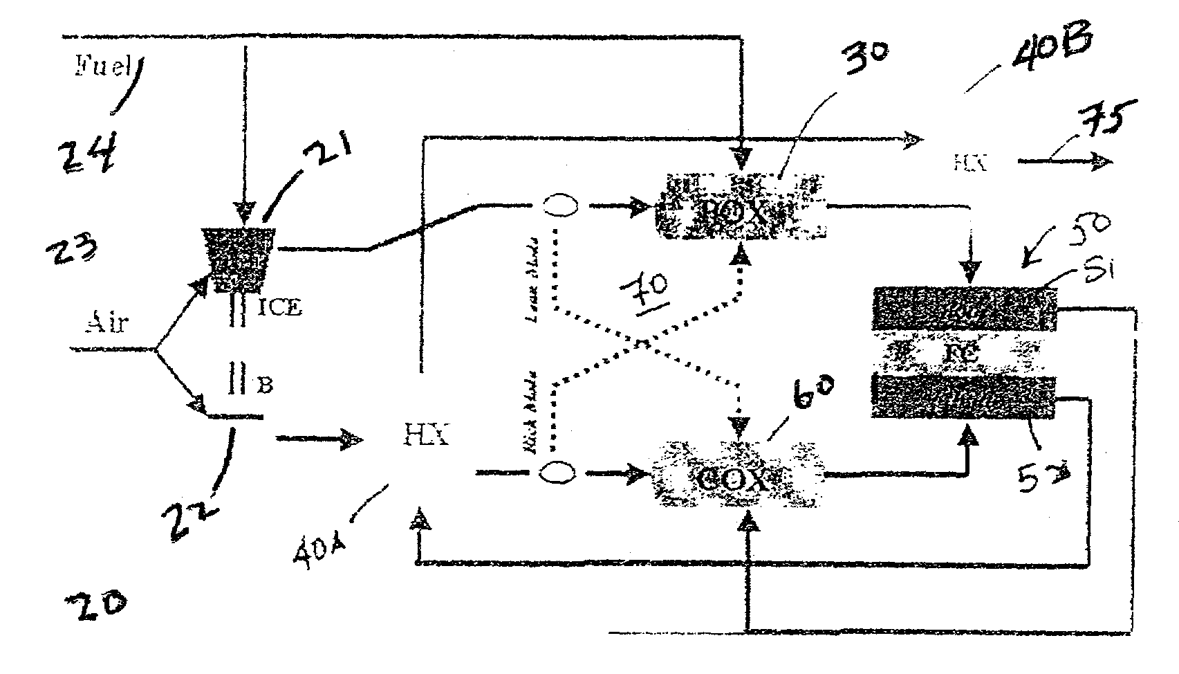
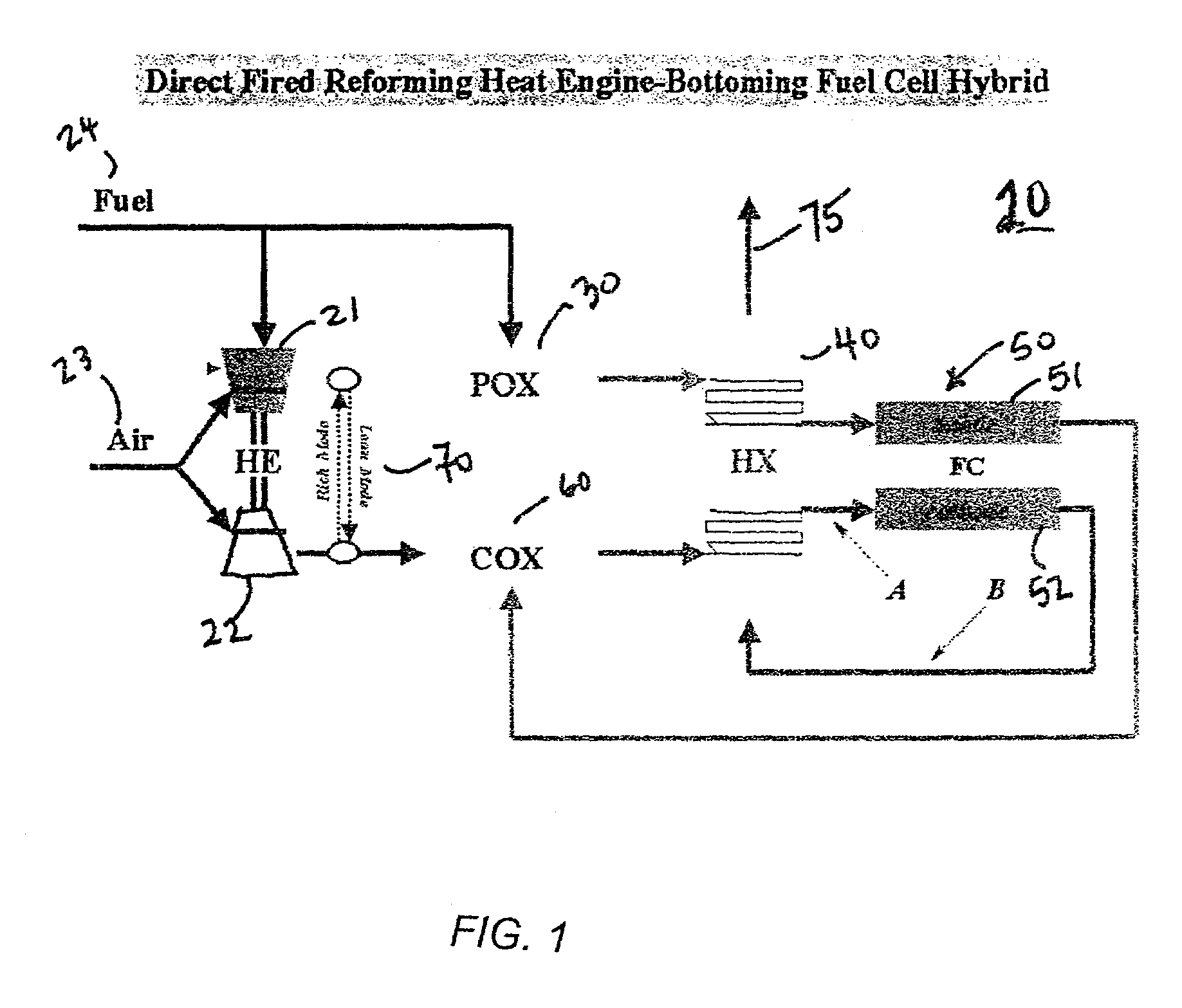
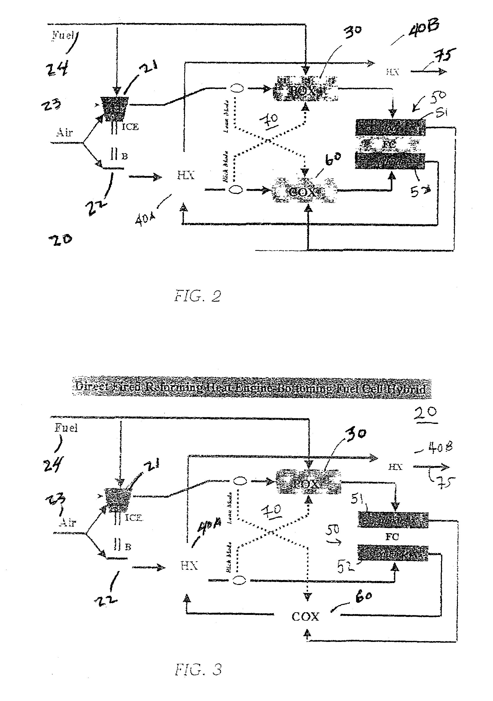
[0011]Referring now to FIG. 1, there is shown a schematic of the major components of the present invention; however, the actual locations of the spent fuel combustion and the NOX reduction are optional and variable. Spent fuel combustion is shown in the figure as occurring in oxidizing reactor, either catalytic or non-catalytic, (COX) upstream of the high temperature heat exchanger HX, but the COX may be located downstream of the HX, before or after the cathode (locations A and B, respectively). The NOX reduction options include the reformer, either catalytic or autothermal (POX), COX reactor, and the anode itself.

[0012]More specifically, the hybrid system 20 illustrated in FIG. 1 may include an internal combustion engine 21 and a blower 22, both connected to a source of air 23. The heat engine or internal combustion engine 21 used as an example herein without limiting the definition of heat engine is also connected to a source of fuel 24. A reformer 30 which may or may not be a cat...


PUM

PropertyMeasurementUnit
temperatureaaaaaaaaaa

Abstract

A system of a fuel cell bottoming an internal combustion engine. The engine exhaust gas may be combined in varying degrees with air and fed as input to a fuel cell. Reformer and oxidizers may be combined with heat exchangers to accommodate rich and lean burn conditions in the engine in peaking and base load conditions without producing high concentrations of harmful emissions.

Description

CONTRACTUAL ORIGIN OF THE INVENTION[0001]The United States Government has rights in this invention pursuant the employer-employee relationship of the Government to the inventors as U.S. Department of Energy employees at the National Energy Technology Laboratory.BACKGROUND OF THE INVENTION[0002]This invention relates to hybrid engine systems including a combination of heat engine such as an internal combustion engine and a fuel cell where the fuel cell bottoms the heat engine. Although hybrid engine systems have been discussed in the past, the prior art has always combined an internal combustion or turbine as a bottom to a fuel cell. The present invention reverses the order and obtains many benefits by using a fuel cell as a bottom to a heat engine such as a direct fired reciprocating engine.SUMMARY OF THE INVENTION[0003]This invention offers a simple means of significantly improving the fuel efficiency, power density, and environmental performance of reciprocating engines in the 1–1...

Claims


Application Information

Patent Timeline
Patent Type & Authority Patents(United States)
IPC IPC(8): H01M8/06F02B43/00H01M8/04
CPCH01M8/04014H01M8/04089H01M8/0606H01M8/0662Y02T90/32H01M8/04111H01M8/0618H01M8/0625H01M2008/1293H01M2008/147H01M2250/20H01M2250/407Y02E60/50Y02E60/525Y02E60/526Y02E60/563H01M8/04022Y02T90/40
Inventor GEISBRECHT, RODNEY A.HOLCOMBE, NORMAN T.
Owner THE UNITED STATES AS REPRESENTED BY THE DEPARTMENT OF ENERGY
Why Eureka
Try Eureka