Video camera with major functions implemented in host software

a video camera and host software technology, applied in the field of video cameras, can solve the problems of reducing the amount of data that has to be compressed and sent over the bus, limiting the bandwidth of data that can be sent, and defective detector positions that do not properly collect light, etc., to achieve the effect of increasing the volume of raw data, reducing the cost, and increasing the bandwidth

Inactive Publication Date: 2006-02-07
LOGITECH EURO SA
View PDF66 Cites 57 Cited by
  • Summary
  • Abstract
  • Description
  • Claims
  • Application Information

AI Technical Summary

Benefits of technology

[0021]The present invention provides a low cost camera by implementing the major functions in host software. This is accomplished by sending raw, digitized data from the camera directly to the host. The increased volume of raw data is handled by either an improved compression / decompression scheme using lossless compression, using lossy compression or using a shared bus with higher bandwidth. By moving such functions as color processing and scaling to the host, the pixel correction can also be moved to the host. This in turn allows the elimination of the frame buffer memory from the camera. Finally, the camera can use a low cost lens by implementing vignetting correction with a vignetting correction value stored in a register of the camera for later access by the host to perform corrections.
[0022]In one embodiment, the host decompresses the transmitted data by using a processor with the capability of simultaneous operations on multiple packed pixel values, such as the Intel MMX™ technology. This maintains a sufficient decompression speed for a larger amount of data with minimal impact on the frame rate. In one embodiment, a group of bits from the data stream are duplicated and provided to multiple positions in a register, where they can be simultaneously compared to multiple maximum values. This allows a quick determination of how many bits of the variable bit encoding correspond to a pixel value.
[0023]In an embodiment using lossy compression, vignetting, gamma, distortion or aliasing correction and pixel correction are performed in the camera itself, since the ability to correct would be degraded by the loss of information during the lossy compression / decompression process. However, the color processing, scaling and other operations are still performed in the host, achieving a low cost camera which does not require a frame buffer memory and color processing and scaling circuitry.
[0024]In one embodiment, the camera can be made low-cost by using a low-cost lens even though it has vignetting distortion. This is accomplished by providing a memory element, such as a register, in the camera. This memory element is programmed at the time of manufacture with a value corresponding to the amount of vignetting or correction required. The register can then be read by the host during operation to determine the amount of correction required in a vignetting correction algorithm executed in the host on the received data prior to any other processing. In an alternate embodiment, the memory element can store a correction or value factor for other defects in the lens or other aspects of the camera. For example, an indication of bad pixel sites could be stored for subsequent reading and correction by the host.

Problems solved by technology

This limits the bandwidth of data that can be sent, requiring compression of the video data.
Typically, cameras will do some of the preprocessing of the image in the camera electronics, thus both off-loading processing from the CPU of the computer and potentially reducing the amount of data that has to be compressed and sent over the bus.
For example, a CCD or CMOS sensor in the camera may have defective detector positions which do not properly collect light.
This algorithm is, however, not suitable for fast decompression using most of the currently available microprocessors such as Intel®'s Pentium® family.
However, when this effect appears unintentionally in digital photographs, it is annoying.
In addition, the price pressure forces manufacturers to use fewer semiconductor chips, thus making the use of semiconductor memory to store vignetting corrections undesirable.
The processes used to produce image sensors, though highly advanced, are not perfect.
This can result in a displayed image having a dark or black dot, bright white dot or incorrect color dot, all of which are unwanted and are undesirable to the end user.
The defective pixels are produced when or after the image sensor array is manufactured.
The disadvantage of such approaches is the need to incorporate and program memory devices during product assembly and testing which add costs and delays.
Additionally, the hardware device costs will also increase due to the need to add the correcting circuitry or logic to the video processing application specific integrated circuit (ASIC).
These methods typically rely on rather sophisticated and expensive systems and computer software to detect and correct bad pixels.
Besides requiring user input, such approaches are also expensive, tedious and very time consuming.

Method used


Image

  • Video camera with major functions implemented in host software
  • Video camera with major functions implemented in host software
  • Video camera with major functions implemented in host software

Examples


Embodiment Construction

I. Overall System.

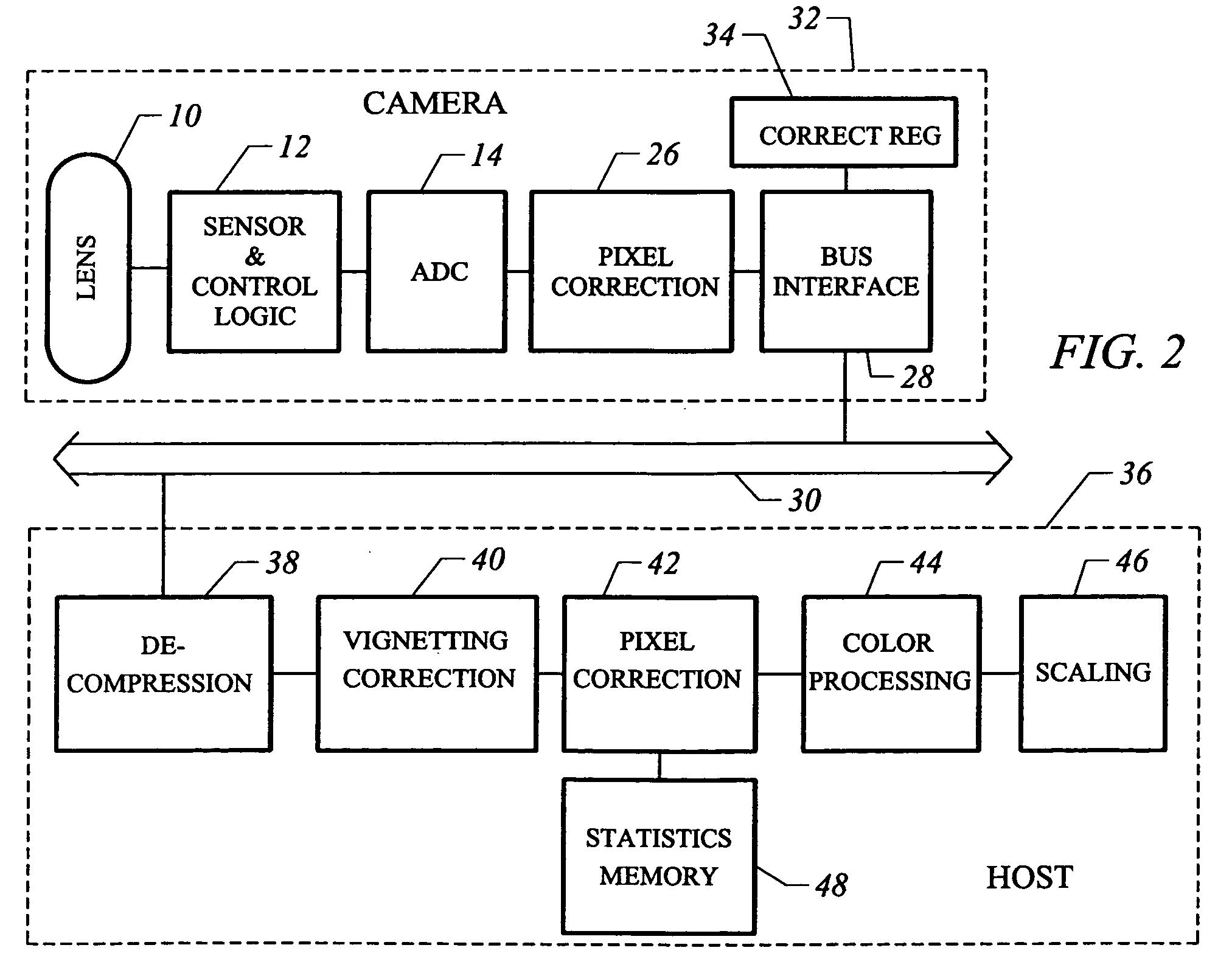
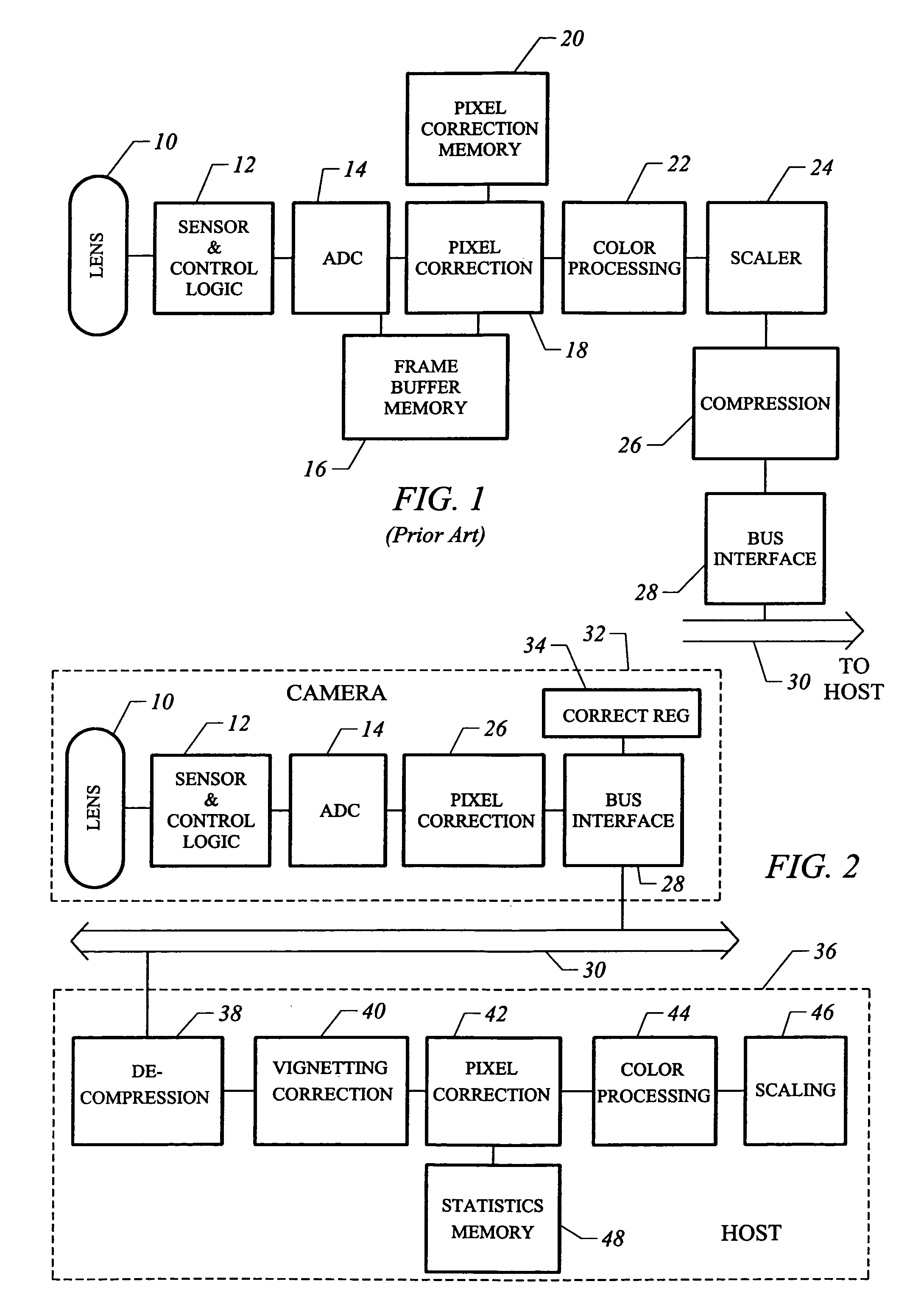
[0040]FIG. 2 is a block diagram of one embodiment of the invention. A camera 32 includes a lens 10, a sensor and control logic 12, and an ADC 14, as in the prior art. However, the other major functions are removed, except for a compression block 26 and bus interface 28. In addition, a correction register 34 is added to store a value corresponding to the vignetting of lens 10.

[0041]The camera connects over a shared bus 30 to host 36. In host 36, the blocks shown are programming blocks executed by the processor of host 36. These are a decompression block 38, a vignetting correction block 40, a pixel correction block 42, a color processing block 44 and a scaling block 46. Also shown is a statistics memory 48, which can be a portion of the host memory, for storing statistics information on pixels needing correction.

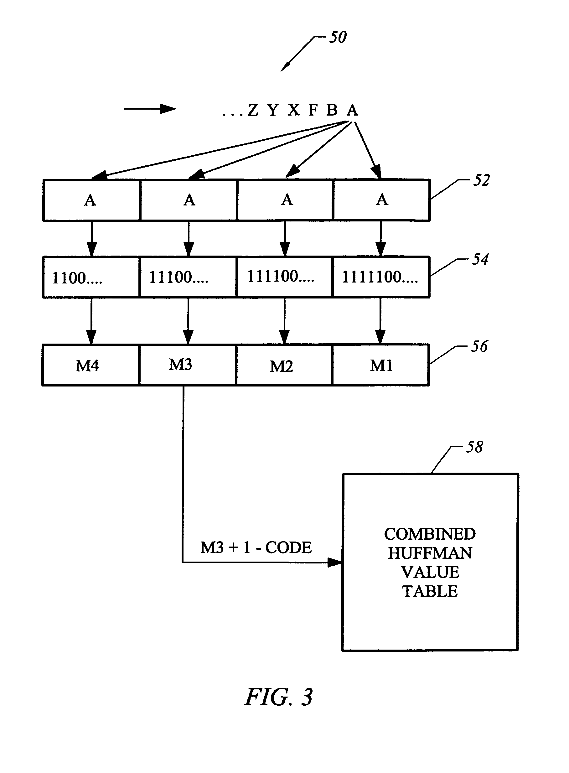
II. Huffman Decompression.

[0042]Preferably, the processor used by host 36 includes the ability to perform operations on multiple packed pixels in a single r...


PUM


Abstract

A low cost camera by implementing the major functions in host software is provided. This is accomplished by sending raw, digitized data from the camera directly to the host. The increased volume of raw data is handled by either an improved compression / decompression scheme using lossless compression, using lossy compression or using a shared bus with higher bandwidth. By moving such functions as color processing and scaling to the host, the pixel correction can also be moved to the host. This in turn allows the elimination of the frame buffer memory from the camera. Finally, the camera can use a low cost lens by implementing vignetting, distortion, gamma or aliasing correction with a correction value stored in a register of the camera for later access by the host to perform corrections.

Description

CROSS-REFERENCES TO RELATED APPLICATIONS[0001]This application is a continuation-in-part of application Ser. No. 09 / 345,167, filed Jun. 30, 1999 now U.S. Pat. No. 6,833,862, entitled “IMAGE SENSOR BASED VIGNETTING CORRECTION”, application Ser. No. 09 / 464,364, filed Dec. 15, 1999, entitled “DYNAMIC ANOMALOUS PIXEL DETECTION AND CORRECTION”, and application Ser. No. 09 / 343,934 now U.S. Pat. No. 6,580,828, filed Jun. 30, 1999, entitled “FAST DECODING”. All of which are incorporated herein by reference.BACKGROUND OF THE INVENTION[0002]The present invention relates to video cameras, and in particular to video cameras connected to a computer or other intelligent device by a shared interface, such as the universal serial bus (USB).[0003]Video cameras for providing both still pictures and motion pictures have been developed which can connect to a computer to provide a digitized image. Such cameras can be connected to the computer via a shared bus, such as the USB. This limits the bandwidth ...

Claims


Application Information

Patent Timeline
Patent Type & Authority Patents(United States)
IPC IPC(8): H04N5/217H04N9/64H03M7/40H04N5/228H04N5/232H04N5/367H04N7/26
CPCH04N5/232H04N5/23229H04N19/00H04N5/367H04N21/4143H04N5/3572H04N23/661H04N23/80H04N25/61H04N25/68H04N2201/001
Inventor HSU, MARKNORCROSS, MITCHELLAUBERGER, GEORGESZIMMERMANN, REMYMAGGI, SERGIOSANCHEZ, GEORGEBILLERBECK, BRYEDLI, WEILABROUSSE, JEAN-MICHEL JUNIEN
Owner LOGITECH EURO SA
Why Eureka
Try Eureka