
Tuned bandwidth photocathode for transmission negative electron affinity devices

a negative electron affinity and transmission cathode technology, applied in the direction of radiation control devices, tubes with screens, image-conversion/image-amplification tubes, etc., can solve the problems of reducing the diffusion lifetime of photo excited electrons and drastically reducing the photo sensitivity (photo response)

Inactive Publication Date: 2006-02-14
ELBIT SYSTEMS OF AMERICA LLC
View PDF14 Cites 5 Cited by
  • Summary
  • Abstract
  • Description
  • Claims
  • Application Information

AI Technical Summary

Problems solved by technology

In practice, however, defects in the GaAs material and at the GaAs / glass interface decrease the diffusion lifetime of photo excited electrons.
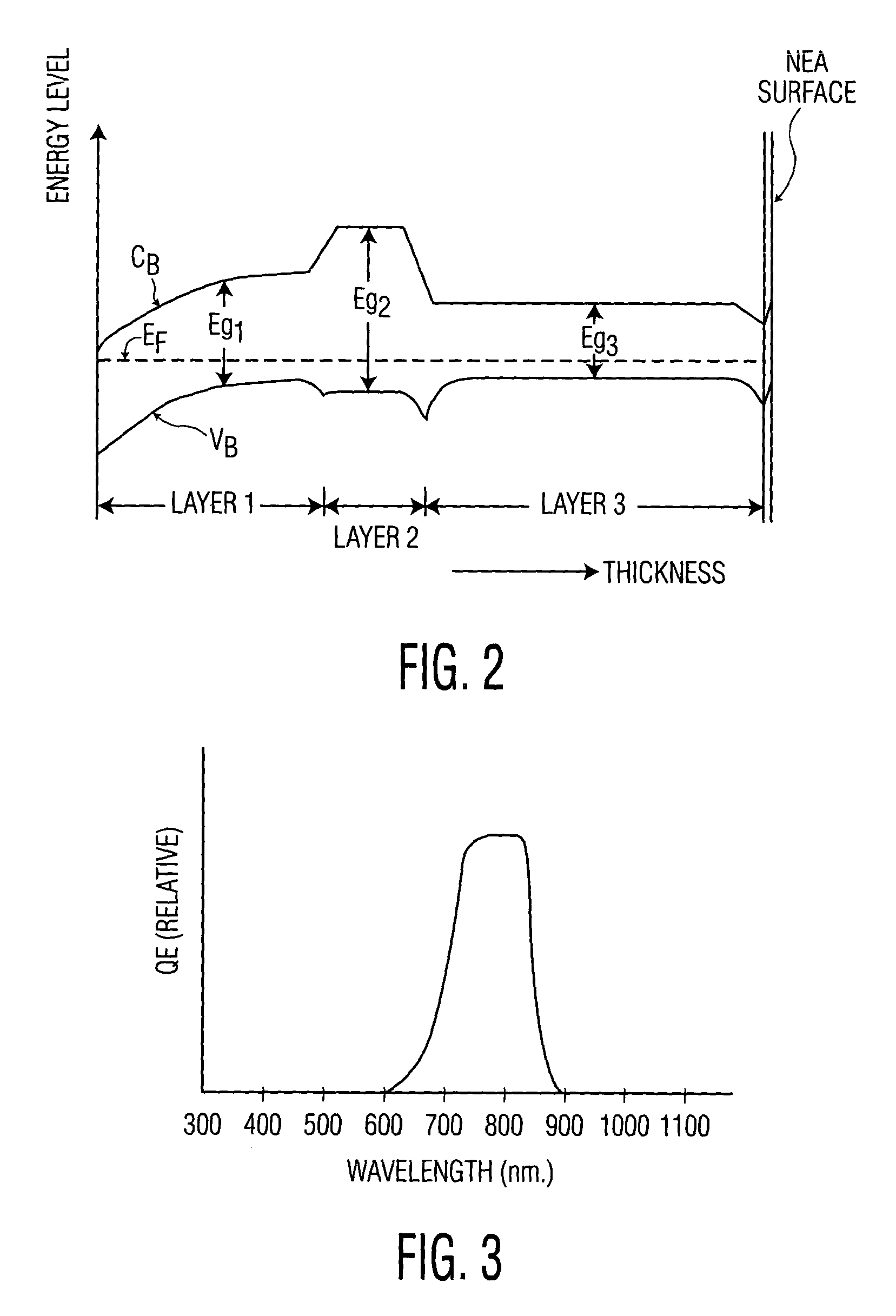
This may drastically reduce the photo sensitivity (photo response), especially at the short wavelength region of FIG. 5.

Method used


Image

  • Tuned bandwidth photocathode for transmission negative electron affinity devices
  • Tuned bandwidth photocathode for transmission negative electron affinity devices
  • Tuned bandwidth photocathode for transmission negative electron affinity devices

Examples


Embodiment Construction

[0031]As will be explained, the present invention provides a transmission NEA photocathode that has a tuneable photosensitivity, or a tuneable spectral-response characteristic. The spectral bandwidth and the spectral center wavelength may be tuned to desired values over a broad range. The invention provides short and long wavelength cutoffs, which may be tuned, without the need for external filtering optics.

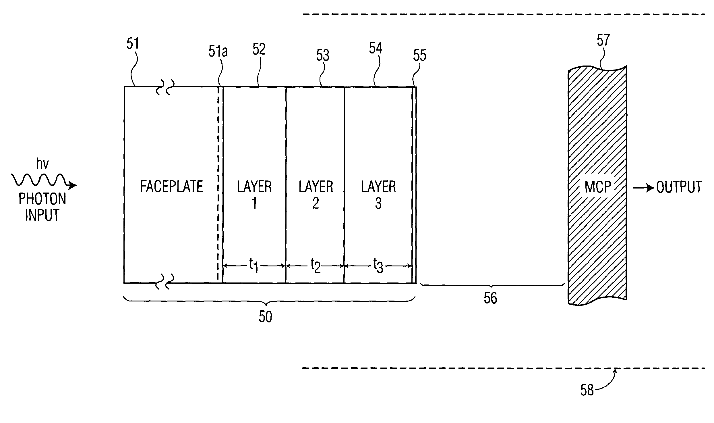
[0032]Referring to FIG. 1, there is shown a cross section of a NEA transmission photocathode, generally designated as 50, in accordance with an embodiment of the invention. As shown, photocathode 50 includes faceplate 51, layer 1 (52), layer 2 (53), layer 3 (54) and NEA layer55. Photocathode 50 is inserted into vacuum housing 58, which may be similar to the manner in which photocathode 12 is inserted into vacuum housing 22 of FIG. 6. Microchannel plate 57 is also shown inserted into vacuum housing 58, in a manner similar to that of microchannel plate 24 shown inserted into vacuum...


PUM


Abstract

A photocathode includes a first layer having a first energy band gap for providing absorption of light of wavelengths shorter than or equal to a first wavelength, a second layer having a second energy band gap for providing transmission of light of wavelengths longer than the first wavelength, and a third layer having a third energy band gap for providing absorption of light of wavelengths between the first wavelength and a second wavelength. The first wavelength is shorter than the second wavelength. The first, second and third layers are positioned in sequence between input and output sides of the photocathode.

Description

TECHNICAL FIELD[0001]The present invention relates, in general, to a transmission photocathode device and, more specifically, to a negative electron affinity (NEA) transmission device, whose spectral response may be tuned over a broad spectral range.BACKGROUND OF THE INVENTION[0002]There are many devices for detecting radiation. In one type of detector, photocathodes are used with microchannel plates (MCPs) to detect low levels of electromagnetic radiation. Photocathodes emit electrons in response to exposure to photons. The electrons can then be accelerated by electrostatic fields toward a microchannel plate. The microchannel plate produces cascades of secondary electrons in response to incident electrons. A receiving device then receives the secondary electrons and sends out a signal responsive to the electrons. Since the number of electrons emitted from the microchannel plate is much larger than the number of incident electrons, the signal produced by the device is amplified for ...

Claims


Application Information

Patent Timeline
IPC IPC(8): H01L29/12H01J1/00H01J9/12H01J31/50H01J40/06H01J43/08H01L21/00H01L27/146
CPCH01J9/12H01J43/08H01J31/506H01J1/34
Inventor SILLMON, ROGER S.SMITH, ARLYNN W.BENZ, RUDY G.
Owner ELBIT SYSTEMS OF AMERICA LLC
Learn More