Packet switching apparatus

a technology of packet data communication and switch apparatus, which is applied in the field of packet data communication apparatus, can solve the problems of difficult to expand or decrease the switch capacity or maintain the switch apparatus without interrupting communication service, and literature 1 does not disclose a redundancy of switch configuration, etc., and achieves high throughput and large capacity. , the effect of large capacity

Inactive Publication Date: 2006-02-14
HITACHI LTD
View PDF6 Cites 39 Cited by
  • Summary
  • Abstract
  • Description
  • Claims
  • Application Information

AI Technical Summary

Benefits of technology

[0012]An object of the present invention is to provide a packet communication apparatus with high throughput and large capacity. More particularly, an object of the present invention is to provide a packet communication apparatus with large capacity and high throughput even when ATM cells or short packets are input successfully.

Problems solved by technology

Therefore, when expansion switch planes are added without stopping the operation of the ATM switch, there is a possibility that the order of cells is reversed due to discrepancy in buffering state among switch planes.
Thus, it is difficult to expand or decrease the switch capacity or maintain the switch apparatus without interrupting communication service.
Furthermore, literature 1 does not disclose a redundancy of switch configuration.
However, when constructing an ultra-large capacity switch to support high-speed transmission lines in near future, in crossbar switches that use ATM cells or cells obtained by dividing variable length packets (cells are hereafter referred to data of short fixed lengths of about 64 bytes) as processing units will have a bottleneck of scheduling time that decides connection relationship of input and output ports cell by cell.
Therefore, it will become difficult to configure a crossbar switch with high throughput.
Moreover, literature 2 does not disclose how to expand or decrease the switch capacity, or perform maintenance of the switch nor does it disclose a redundancy of switch configuration.
Therefore, it is difficult to configure a packet communication apparatus in a compact size and at low cost.
Moreover, literature 4 does not disclose how to expand or decrease the switch capacity, or how to perform maintenance of the switch apparatus without interrupting communication service.

Method used


Image

  • Packet switching apparatus
  • Packet switching apparatus
  • Packet switching apparatus

Examples


Embodiment Construction

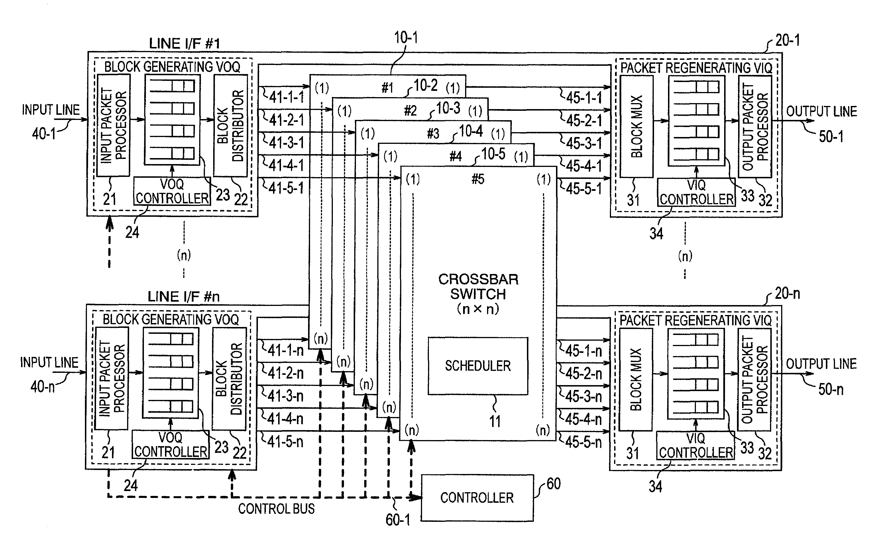
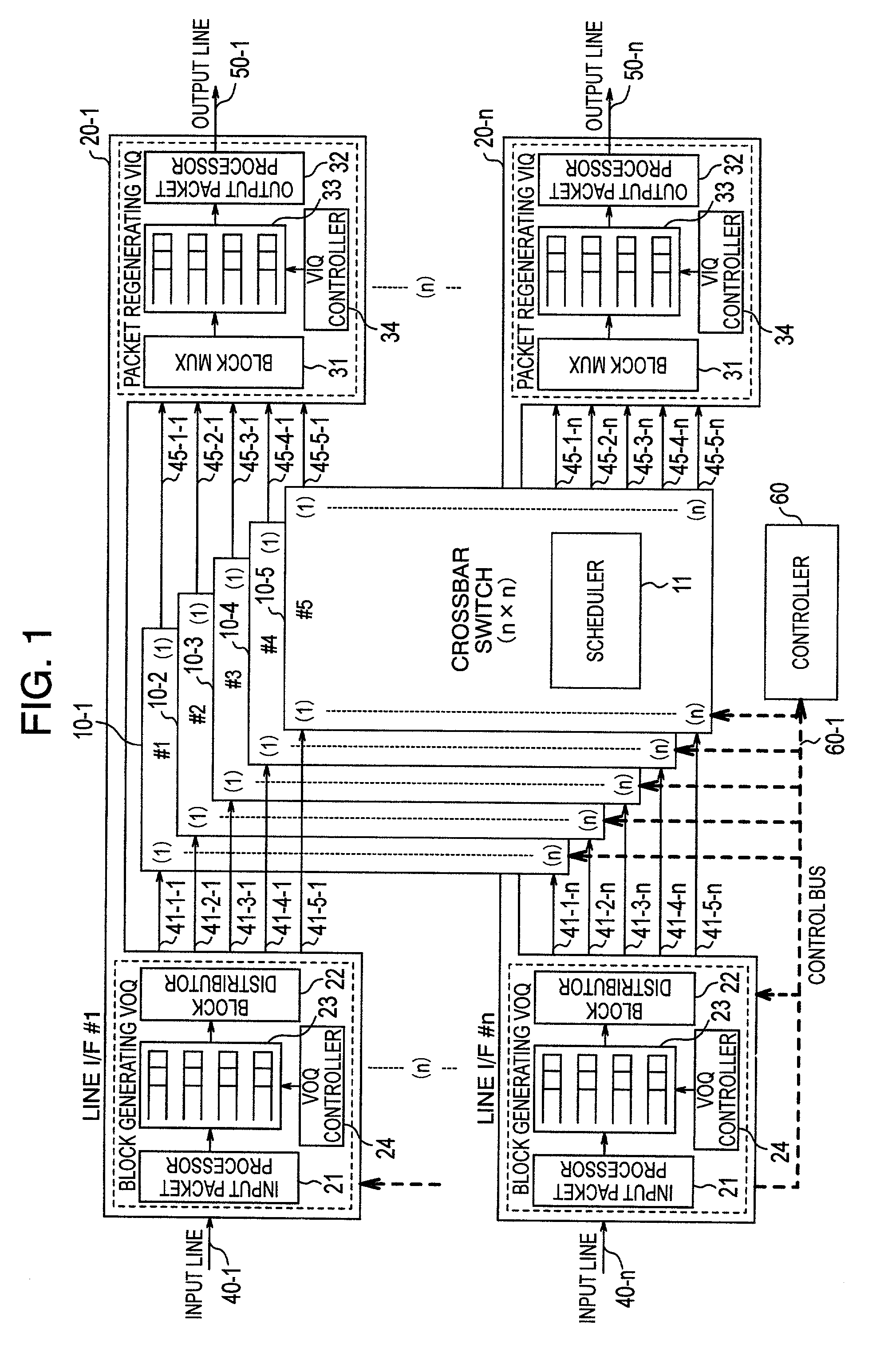
[0047]Description will be made of an embodiment of a packet switch according to one embodiment of the present invention by taking as an example a packet switch comprising five planes of crossbar switches each having a specific capacity (n×n). Even when a largest number of line interfaces that are mountable on this packet switch are mounted, four planes of crossbar switches are supposed to be sufficient in respect of processing capacity. More specifically, if four switch planes are used, it is assumed that the switching performance is not deteriorated, such as being suffered internal blocking of input traffic. Description will be made later on how to use one extra switch plane, which is not necessary in terms of switch capacity.

[0048]FIG. 1 is a diagram showing a configuration example of a packet switch according to one embodiment of the present invention. This packet communication apparatus includes a plurality of crossbar switches 10-1˜10-5, provided with n input ports and n output...


PUM


Abstract

A packet switch has a switch section formed by a plurality of crossbar switch planes and plurality of interfaces, and each interface outputs in parallel input packets in block units to the plurality of crossbar switch planes in response to signals from a scheduler, wherein when n crossbar switch planes can be mounted on the packet switch, each interface allocates time slots corresponding to the n crossbar switch planes or when a switch plane is additionally mounted, a block is read at a time slot corresponding to the additional switch plane or when a switch plane is stopped from working, an idle time slot is used to prevent a block from being output to the switch plane which is unused.

Description

BACKGROUND OF THE INVENTION[0001]The present invention relates to a packet data communication apparatus for switching variable-length packets in data transmission of IP (Internet Protocol), for example, and fixed-length packets (generally called cells) in data transmission of ATM (Asynchronous Transfer Mode).[0002]Nowadays, data traffic is increasing on networks, especially, on the Internet. There are moves toward executing high-quality and high-reliability services such as transaction processes which have been done on leased lines, on the Internet for the purpose of cost reduction. To cope with this tendency, there have been demands for larger capacity, higher speed and improved reliability of packet data communication apparatus as well as the transmission lines.[0003]JP-A-11-154954 published on Jun. 8, 1999 (corresponding to U.S. Ser. No. 08 / 193,414 and EP 0918419A; hereafter referred to as Literature 1) discloses a technology regarding for increasing the capacity of an ATM switch...

Claims


Application Information

Patent Timeline
Patent Type & Authority Patents(United States)
IPC IPC(8): G01R31/08H04Q3/52H04L12/931H04L12/937H04L12/939
CPCH04L49/101H04L49/1576H04L49/1523H04L49/45H04L49/3045H04L49/3072H04L49/3027
Inventor MORIWAKI, NORIHIKOTOYODA, HIDEHIROTAKASE, MASAYUKI
Owner HITACHI LTD
Why Eureka
Try Eureka