Clock data recovery deserializer with programmable SYNC detect logic

a clock data and logic technology, applied in the direction of pulse manipulation, pulse technique, code conversion, etc., can solve the problems of serdes transceivers, inability to recognize the synchronization bit pattern of different communication protocols, and inability to minimize bit error rates for different communication protocols

Active Publication Date: 2006-02-14
LATTICE SEMICON CORP
View PDF10 Cites 53 Cited by
  • Summary
  • Abstract
  • Description
  • Claims
  • Application Information

AI Technical Summary

Problems solved by technology

One of the drawbacks of conventional SERDES transceivers is their inability to recognize synchronization bit patterns of different communications protocols.
Another drawback of conventional SERDES transceivers is their inability to minimize bit error rates for different communications protocols. FIG. 4 shows the prior art components of the clock recovery phase locked loop 112 of FIG. 2 including a phase detector 120, a digital filter 122, and a phase selector 124 for generating the recovered serial clock signal (SCLK) from the high speed serial data input (SDIN).
However, such manufacture of various SERDES transceiver to accommodate different communications protocols may be costly.
A third drawback of conventional SERDES transceivers is their inability to provide additional phases of the recovered clock signal (SCLK) without minimized consumption of increased chip area and power since each additional phase interpolator consumes additional chip area and power.

Method used


Image

  • Clock data recovery deserializer with programmable SYNC detect logic
  • Clock data recovery deserializer with programmable SYNC detect logic
  • Clock data recovery deserializer with programmable SYNC detect logic

Examples


Embodiment Construction

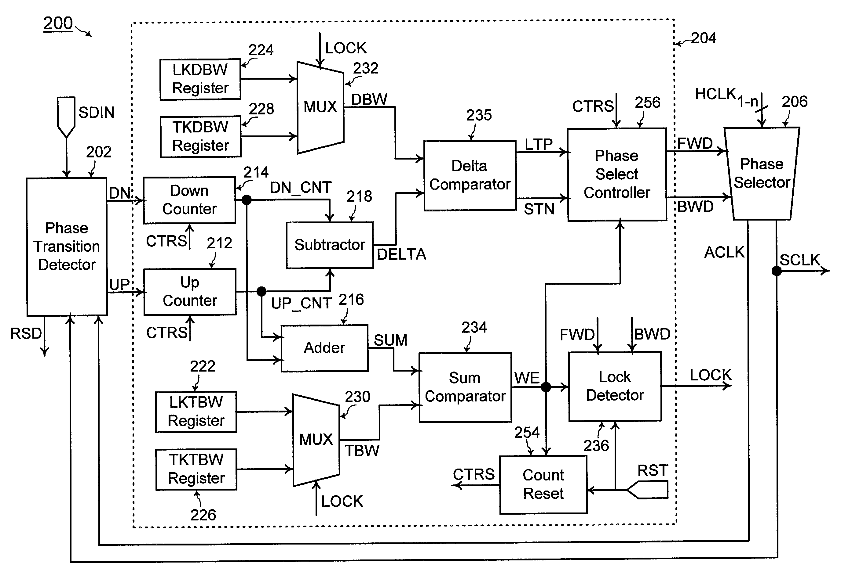
[0057]Referring to FIG. 6, a clock recovery phase locked loop 200 of an embodiment of the present invention includes a phase transition detector 202, a digital filter 204, and a phase selector 206. The phase selector 206 receives a predetermined number of given clock signals (HCLK1-n) such as the given clock signals (HCLK1-n) of FIG. 5 and generates the recovered serial clock signal (SCLK) and the complementary recovered clock signal (ACLK) that is 180° phase shifted from the recovered serial clock signal (SCLK).

[0058]Referring to FIGS. 6 and 8, the components of the digital filter 204 (shown within dashed lines in FIG. 6) of an embodiment of the present invention and the phase transition detector 202 operate according to the flow chart of FIG. 8. The phase transition detector 202 inputs the high speed serial data input (SDIN), the recovered serial clock signal (SCLK), and the complementary recovered clock signal (ACLK). The high speed serial data input (SDIN), the recovered serial ...


PUM


Abstract

In a CDR (clock data recovery) deserializer, a clock divider receives a recovered clock signal (SCLK) and generates a divided clock signal (RPCLK). The frequency of the divided clock signal is lowered with each cycle of the divided clock signal being generated for each count of cycles of the recovered clock signal up to a predetermined ratio number. A serial-to-parallel shift register shifts in recovered serial data bits with each cycle of the recovered clock signal and outputs the predetermined ratio number of the shifted recovered serial data bits at a predetermined transition of every cycle of the divided clock signal. A SYNC (synchronization) detect logic asserts a VRS (diVider ReSet) signal coupled to the clock divider for controlling the clock divider to generate the predetermined transition for a cycle of the divided clock signal when the VRS signal is asserted. The SYNC detect logic includes a plurality of reloadable register portions for storing a plurality of synchronization bit patterns for a plurality of communications protocol. Each of a plurality of bit pattern comparators inputs an intermediate parallel data output (IPDO) from the shift register with each cycle of the recovered clock signal and compares for every cycle of the recovered clock signal the shifted recovered serial data bits to each of the synchronization bit patterns. A multiplexer selects one of the outputs of the bit pattern comparators as the VRS signal depending on the communications protocol of the recovered serial data bits.

Description

BACKGROUND OF THE INVENTION[0001]1. Field of the Invention[0002]The present invention relates generally to SERDES (serializer / deserializer) transceivers, and more particularly, to a CDR (clock data recovery) deserializer with programmable synchronization bit patterns such that the RPDO (recovered parallel data output) are comprised of properly partitioned bits of the recovered serial data for high speed serial data input (SDIN) of multiple communications protocols.[0003]2. Discussion of the Related Art[0004]FIG. 1 shows a conventional SERDES (serializer / deserializer) transceiver 100 coupled between a high speed data communication media 102 and a low speed data processor 104. The high speed data communication media 102 is for sending serial data bits to the low speed data processor 104 at relatively high speeds. The low speed data processor 104 then receives and processes such data at a lower speed. For example, the high speed data communication media 102 may be a network of optical ...

Claims


Application Information

Patent Timeline
Patent Type & Authority Patents(United States)
IPC IPC(8): H04L7/00
CPCH03K5/135H03M9/00H03L7/0814H03L7/095
Inventor TRINH, JAYSONCHEN, CHIENKUANGCHI, KUANGBECKER, MARK
Owner LATTICE SEMICON CORP
Why Eureka
Try Eureka