Millimeter wave pulsed radar system

Inactive Publication Date: 2006-02-21
REVEAL IMAGING
View PDF12 Cites 221 Cited by
  • Summary
  • Abstract
  • Description
  • Claims
  • Application Information

AI Technical Summary

Benefits of technology

[0005]It is therefore an object of the present invention to provide a millimeter wave (MMW) pulsed radar system that includ

Problems solved by technology

Although some pulsed radar systems are now manufactured from standard components, and the overall prices for these systems have been dramatically reduced, prior art millimeter wave (MMW) pulsed radar systems, however, have been difficult to design and manufacture at low costs.
This difficulty arises because of the difficulty in establishing and/or controlling transmit and receiv

Method used


Image

  • Millimeter wave pulsed radar system
  • Millimeter wave pulsed radar system
  • Millimeter wave pulsed radar system

Examples


Embodiment Construction

[0027]The present invention will now be described more fully hereinafter with reference to the accompanying drawings, in which preferred embodiments of the invention are shown. This invention may, however, be embodied in many different forms and should not be construed as limited to the embodiments set forth herein. Rather, these embodiments are provided so that this disclosure will be thorough and complete, and will fully convey the scope of the invention to those skilled in the art. Like numbers refer to like elements throughout, and prime notation is used to indicate similar elements in alternative embodiments.

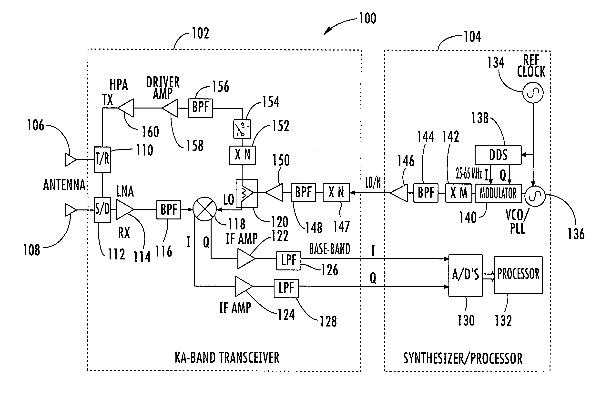
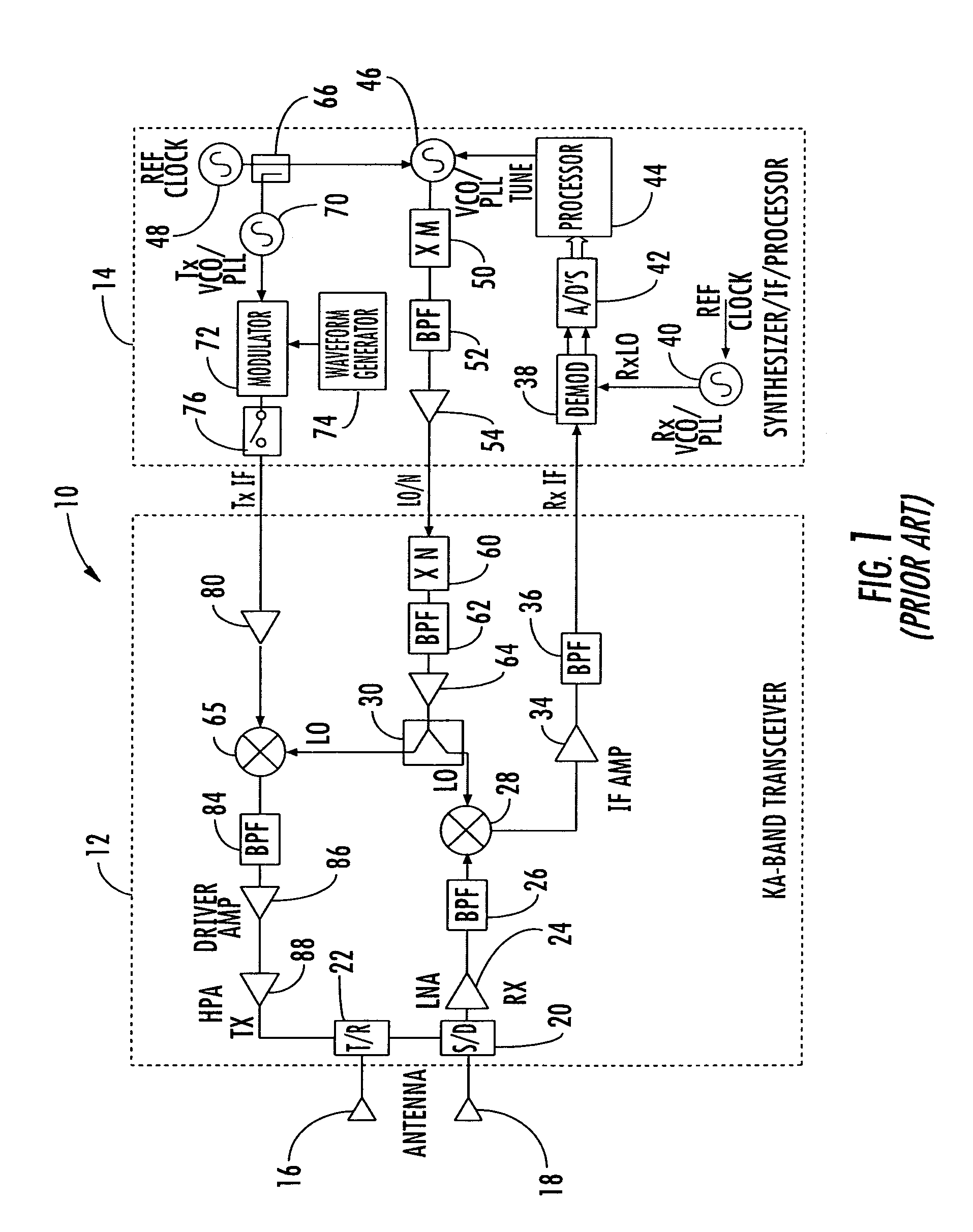
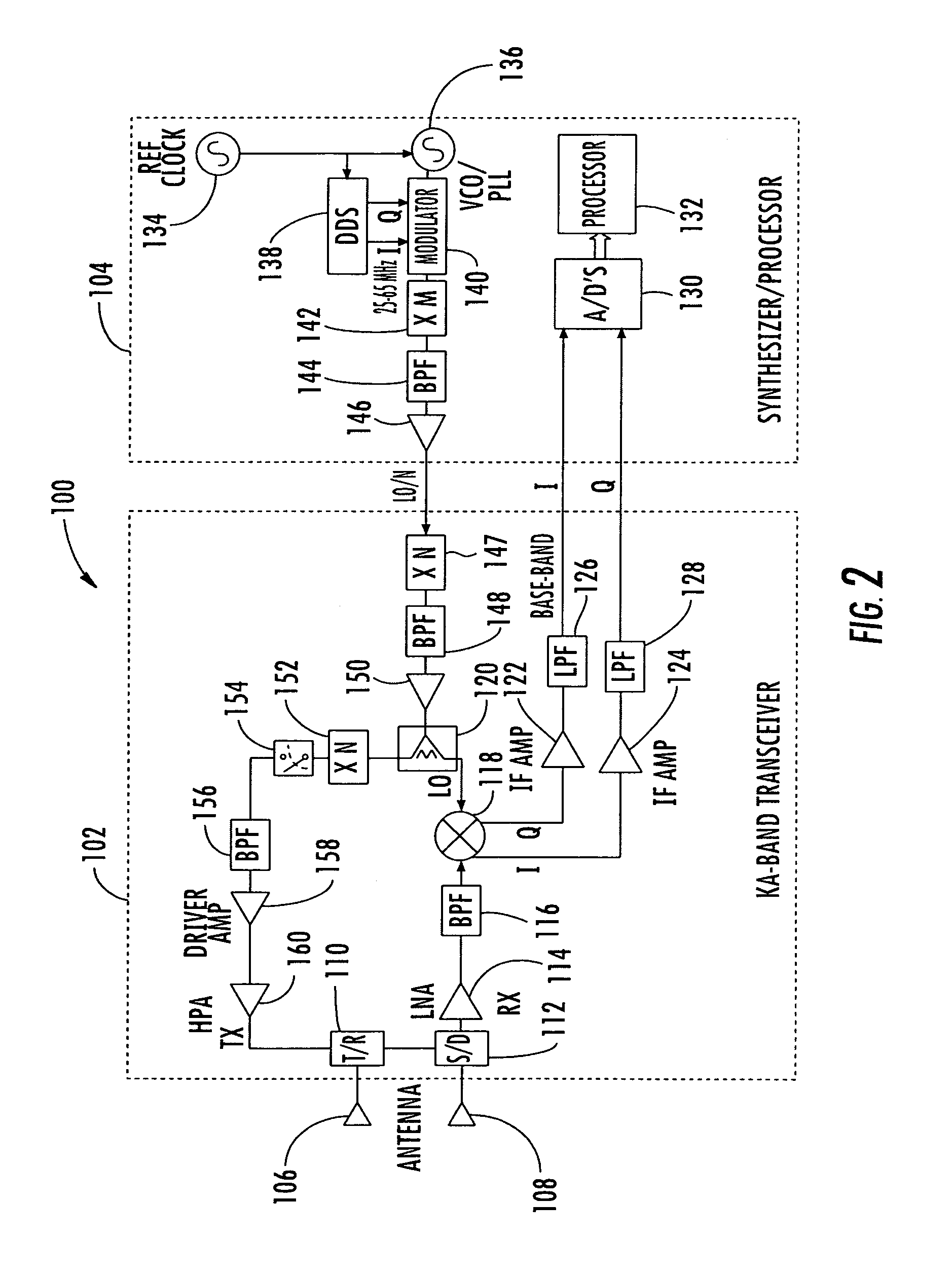
[0028]Traditionally, pulsed millimeter wave (MMW) radar systems have been difficult to design and build in an efficient manner at a low cost. The MMW pulsed radar system of the present invention overcomes the disadvantages of prior art MMW pulsed radar systems by using improved frequency generation circuits, integrated Voltage Controlled Oscillator and Phase Locked Loop (VC...


PUM


Abstract

A millimeter wave pulsed radar system includes a radar synthesizer having a voltage controlled oscillator/phase locked loop (VCO/PLL) circuit, direct digital synthesizer (DDS) circuit and quadrature modulator circuit that are operative to generate an intermediate frequency local oscillator signal (IF/LO signal). A radar transceiver is operative with the radar synthesizer for receiving the IF/LO signal. A transmitter section has a frequency multiplier that multiplies the IF/LO signal up to a millimeter wave (MMW) radar signal and a receiver section and includes a direct conversion mixer that receives a MMW radar signal and the IF/LO signal to produce I/Q baseband signals that are later digitized and processed.

Description

FIELD OF THE INVENTION[0001]The present invention relates to radar systems, and more particularly, the present invention relates to millimeter wave (MMW) pulsed radar systems.BACKGROUND OF THE INVENTION[0002]Pulsed radar systems are different from continuous wave (CW) radars. CW radar systems typically include a transmitter that transmits a continuous flow of radio energy to the target, which re-radiates or scatters this energy and returns a small amount to a receiving antenna. A pulsed radar system, however, transmits a repetitive pattern of short pulses. Typically, a pulsed radar system includes a transmitter, for example, a master-oscillator power amplifier (MOPA) transmitter, and a chain of amplifiers that convert and increase the power level from a supplied electrical power to a transmitted signal power, each controlled by a modulator forming the radar pulse. It is possible in more simple radar systems to use a single high power oscillator with no further amplification. In some...

Claims


Application Information

Patent Timeline
IPC IPC(8): G01S7/28G01S13/10G01S7/40
CPCG01S7/032G01S13/28G01S7/282G01S2007/2886G01S7/2886
Inventor AMMAR, DANNY F.BILLS, DAVID M.CLARK, GAVINSHAFIE, MATT H.
Owner REVEAL IMAGING
Why Eureka
Try Eureka