
Method and apparatus for interleaved processing of direct and indirect texture coordinates in a graphics system

a graphics system and texture technology, applied in the field of interactive graphics systems, can solve the problems of complex computer graphics generation, inability to interact with the computer doing the graphics generation, and high cost of computer-generated three-dimensional graphics a few years ago, so as to reduce yield and reliability, add to the overall production cost of the system, and efficiently implement

Inactive Publication Date: 2006-02-21
NINTENDO CO LTD
View PDF456 Cites 228 Cited by
  • Summary
  • Abstract
  • Description
  • Claims
  • Application Information

AI Technical Summary

Benefits of technology

This approach enables efficient and flexible texture coordinate processing and retrieval, reducing hardware complexity while maintaining fine granularity in data processing, thereby enhancing the repertoire of texturing capabilities in 3D graphics systems.

Problems solved by technology

Because computer graphics generation is complex, computer-generated three-dimensional graphics just a few years ago were mostly limited to expensive specialized flight simulators, high-end graphics workstations and supercomputers.
The public saw some of the images generated by these computer systems in movies and expensive television advertisements, but most of us couldn't actually interact with the computers doing the graphics generation.
A problem graphics system designers confronted in the past was how to create realistic looking surface detail on a rendered object without resorting to explicit modeling of the desired details with polygons or other geometric primitives.
Although surface details can be simulated, for example, using myriad small triangles with interpolated shading between vertices, as the desired detail becomes finer and more intricate, explicit modeling with triangles or other primitives places high demands on the graphics system and becomes less practical.
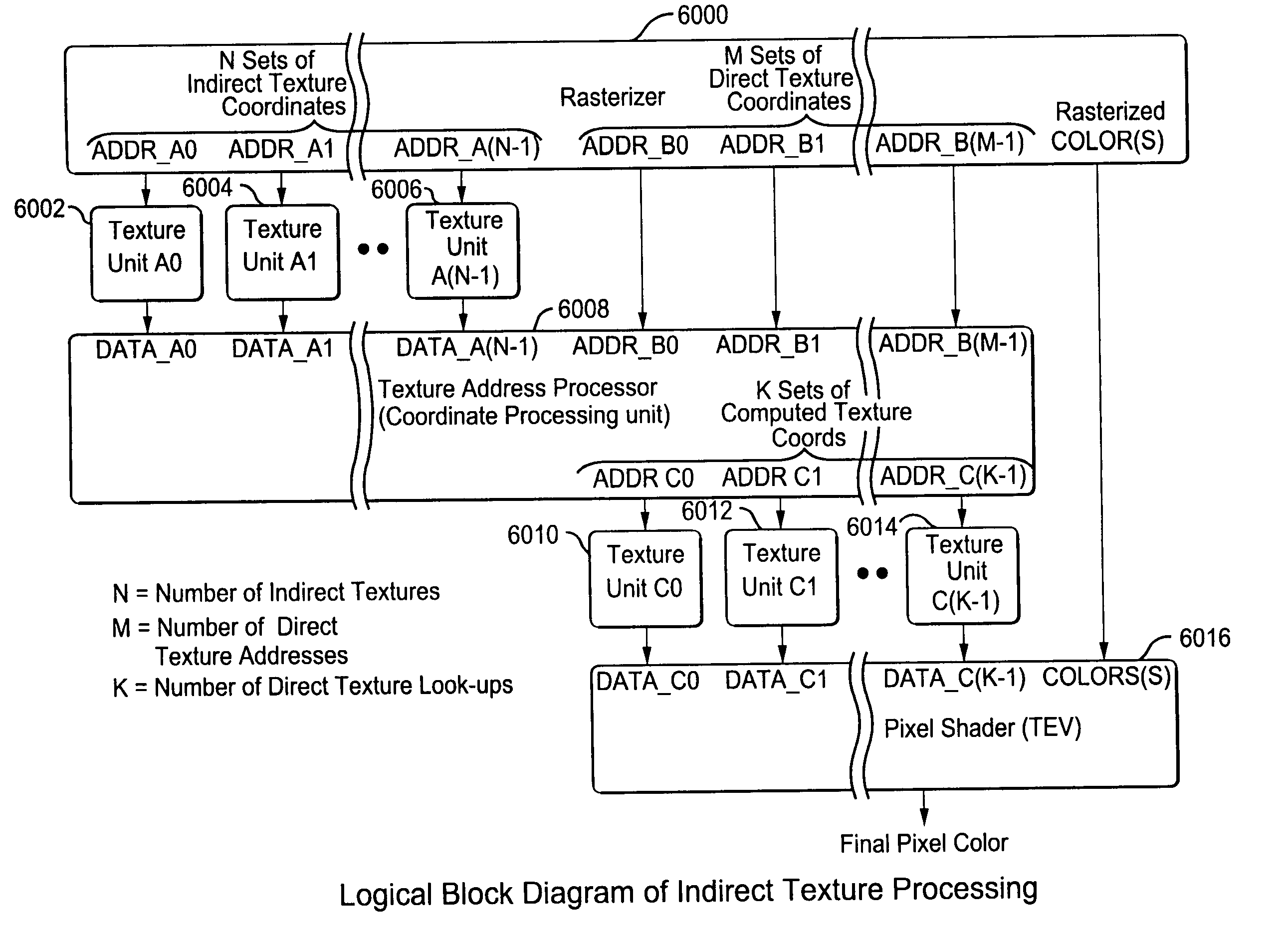
Sophisticated texturing effects utilizing indirect or multiple textures are also possible such as, for example, multi-texturing, meta-textures or texture tiling, but conventional approaches typically involve complex hardware arrangements such as using multiple separate texture retrieval / mapping circuits (units) where the output of one texturing circuit provides the input to a next texturing circuit.
Such duplicated circuitry is essentially idle whenever such effects are not used.
In on-chip graphics processing implementations, the additional circuitry requires more chip real-estate, can reduce yield and reliability, and may significantly add to the overall production cost of the system.
Consequently, a further problem confronting graphics system designers is how to efficiently implement these more sophisticated texturing effects without associated increases in texture mapping hardware complexity.
Although this approach may reduce hardware complexity somewhat, it is fairly time consuming, requires generating / providing the same set of texture coordinates multiple times, and results in inefficient processing during mode changes (e.g., switching between direct and indirect texturing operational modes).
Moreover, this approach results in a very course granularity in the data processing flow through the graphics rendering system—significantly affecting polygon fill rate.

Method used


Image

  • Method and apparatus for interleaved processing of direct and indirect texture coordinates in a graphics system
  • Method and apparatus for interleaved processing of direct and indirect texture coordinates in a graphics system
  • Method and apparatus for interleaved processing of direct and indirect texture coordinates in a graphics system

Examples


example graphics

PIPELINE

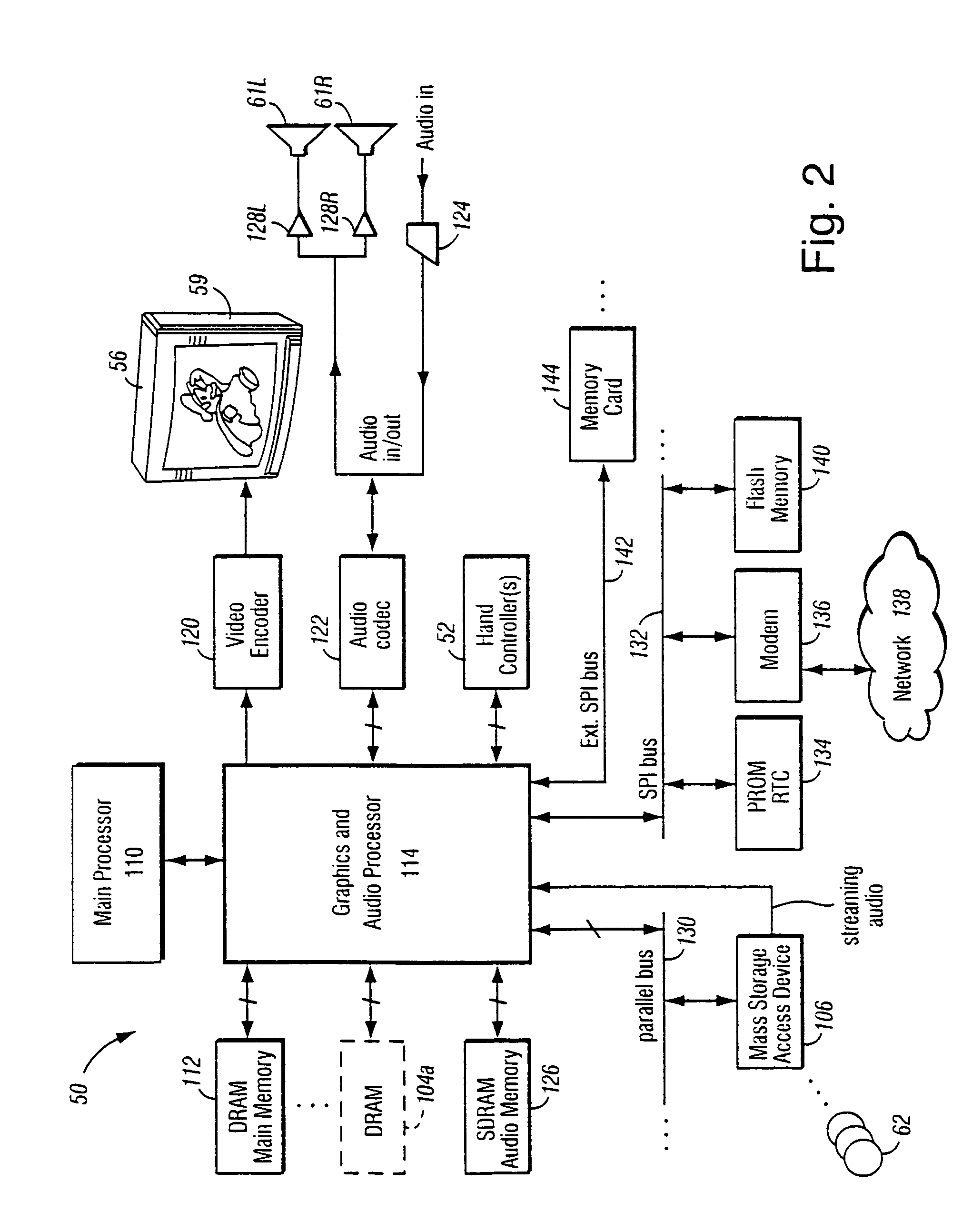
[0077]FIG. 4 shows a more detailed view of an example 3D graphics processor 154. 3D graphics processor 154 includes, among other things, a command processor 200 and a 3D graphics pipeline 180. Main processor 110 communicates streams of data (e.g., graphics command streams and display lists) to command processor 200. Main processor 110 has a two-level cache 115 to minimize memory latency, and also has a write-gathering buffer 111 for non-cached data streams targeted for the graphics and audio processor 114. The write-gathering buffer 111 collects partial cache lines into full cache lines and sends the data out to the graphics and audio processor 114 one cache line at a time for maximum bus usage.

[0078]Command processor 200 parses display commands received from main processor 110—obtaining any additional data necessary to process the display commands from shared memory 112. The command processor 200 provides a stream of vertex commands to graphics pipeline 180 for 2D and / or 3D...

example more

DETAILED IMPLEMENTATION

[0132]FIG. 11 is a flow chart showing an example set of basic processing steps used to perform indirect texture mapping for an example implementation. Most of the steps of FIG. 11 are set up by a general indirect texturing API (application program interface) function 801 that sets parameters for processing an indirect texture by texture unit 500 and texture environment unit 600.

[0133]System 50 first stores a texture image / data in texture memory 502 for use as an indirect texture (block 800). Based on one or more API command functions (blocks 802–810), commander processor 200 then provides a specified set of indirect texture coordinates to texture retrieval unit 500a (see FIG. 5) which accesses texture memory 504 and retrieves indirect texture lookup data (FIG. 7B block 952). In the example embodiment, one or more API indirect texture function(s) 801 allow a graphics application to set up associations between texture maps and texture coordinates and to specify ...

example arguments

[0229]Tev_stage The TEV stage that is being changed.

[0230]Example Usage:[0231]void GXSetTevIndRepeat (GXTevStageID tev_stage);

GXSetAlphaCompare

[0232]This functino sets the parameters for the alpha compare function which uses the alpha output from the last active Texture Environment (TEVk) stage. The number of active TEV stages are specified using GXSetTevStages.

[0233]The output alpha can be used in the blending equation (see GXSetBlendMode) to control how source and destination (frame buffer) pixels are combined.

[0234]The alpha compare operation is:

alpha—pass=(alpha—src(comp0)(ref0)(op)(alpha—src(comp)ref1)[0235]where alpha_src is the alpha from the last active Tev stage. As an example, you can implement these equations:

alpha—pass=(alpha—src>ref0) AND (alpha—src<ref1)

or

alpha—pass=(alpha—src>ref0) OR (alpha—src<ref1)

[0236]The Z compare may occur either before or after texturing. In the case where Z compare is performed before texturing, the Z is written based only the Z t...


PUM


Abstract

A graphics system including a custom graphics and audio processor produces exciting 2D and 3D graphics and surround sound. The system includes a graphics and audio processor including a 3D graphics pipeline and an audio digital signal processor. The graphics pipeline renders and prepares images for display at least in part in response to polygon vertex attribute data and texel color data stored as a texture images in an associated memory. An efficient texturing pipeline arrangement achieves a relatively low chip-footprint by utilizing a single texture coordinate / data processing unit that interleaves the processing of logical direct and indirect texture coordinate data and a texture lookup data feedback path for “recirculating” indirect texture lookup data retrieved from a single texture retrieval unit back to the texture coordinate / data processing unit. Versatile indirect texture referencing is achieved by using the same texture coordinate / data processing unit to transform the recirculated texture lookup data into offsets that may be added to the texture coordinates of a direct texture lookup. A generalized indirect texture API function is provided that supports defining at least four indirect texture referencing operations and allows for selectively associating one of at least eight different texture images with each indirect texture defined. Retrieved indirect texture lookup data is processed as multi-bit binary data triplets of three, four, five, or eight bits. The data triplets are multiplied by a 3×2 texture coordinate offset matrix before being optionally combined with regular non-indirect coordinate data or coordinate data from a previous cycle / stage of processing. Values of the offset matrix elements are variable and may be dynamically defined for each cycle / stage using selected constants. Two additional variable matrix configurations are also defined containing element values obtained from current direct texture coordinates. Circuitry for optionally biasing and scaling retrieved texture data is also provided.

Description

RELATED APPLICATIONS[0001]This application claims the benefit of U.S. Provisional Application, Ser. No. 60 / 226,891, filed Aug. 23, 2000, the entire content of which is hereby incorporated by reference.FIELD OF THE INVENTION[0002]The present invention relates to computer graphics, and more particularly to interactive graphics systems such as home video game platforms. Still more particularly this invention relates to direct and indirect texture mapping / processing in a graphics system.BACKGROUND AND SUMMARY OF THE INVENTION[0003]Many of us have seen films containing remarkably realistic dinosaurs, aliens, animated toys and other fanciful creatures. Such animations are made possible by computer graphics. Using such techniques, a computer graphics artist can specify how each object should look and how it should change in appearance over time, and a computer then models the objects and displays them on a display such as your television or a computer screen. The computer takes care of per...

Claims


Application Information

Patent Timeline
Patent Type & Authority Patents(United States)
IPC IPC(8): G09G5/00G06T17/00G06T15/00G06T15/04
CPCG06T15/04G06T15/005
Inventor LEATHER, MARK M.DREBIN, ROBERT A.VAN HOOK, TIMOTHY J.
Owner NINTENDO CO LTD
Learn More