Micromachined piezoelectric microspeaker and fabricating method thereof

a micro-machined acoustic transducer and piezoelectric technology, applied in the direction of electrical transducers, deaf-aid sets, electric/electrostriction/magnetostriction machines, etc., can solve the problems of difficult thin sheet production, low output pressure and sensitivity of micro-machined acoustic transducers made of these conventional diaphragm materials, etc., to achieve good control, reduce the effect of diaphrag

Inactive Publication Date: 2006-02-21
YI SEUNG HWAN +1
View PDF9 Cites 23 Cited by
  • Summary
  • Abstract
  • Description
  • Claims
  • Application Information

AI Technical Summary

Benefits of technology

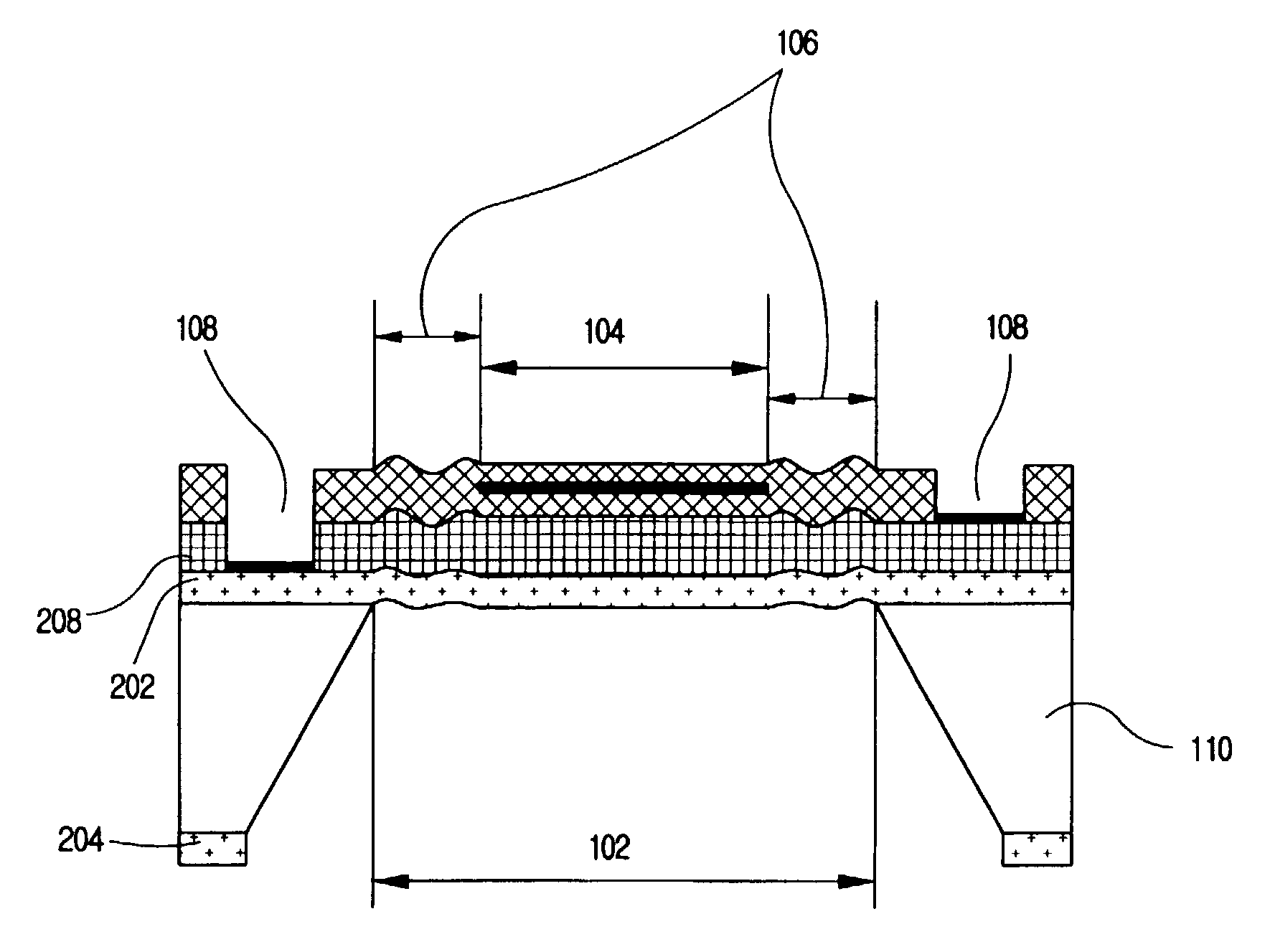
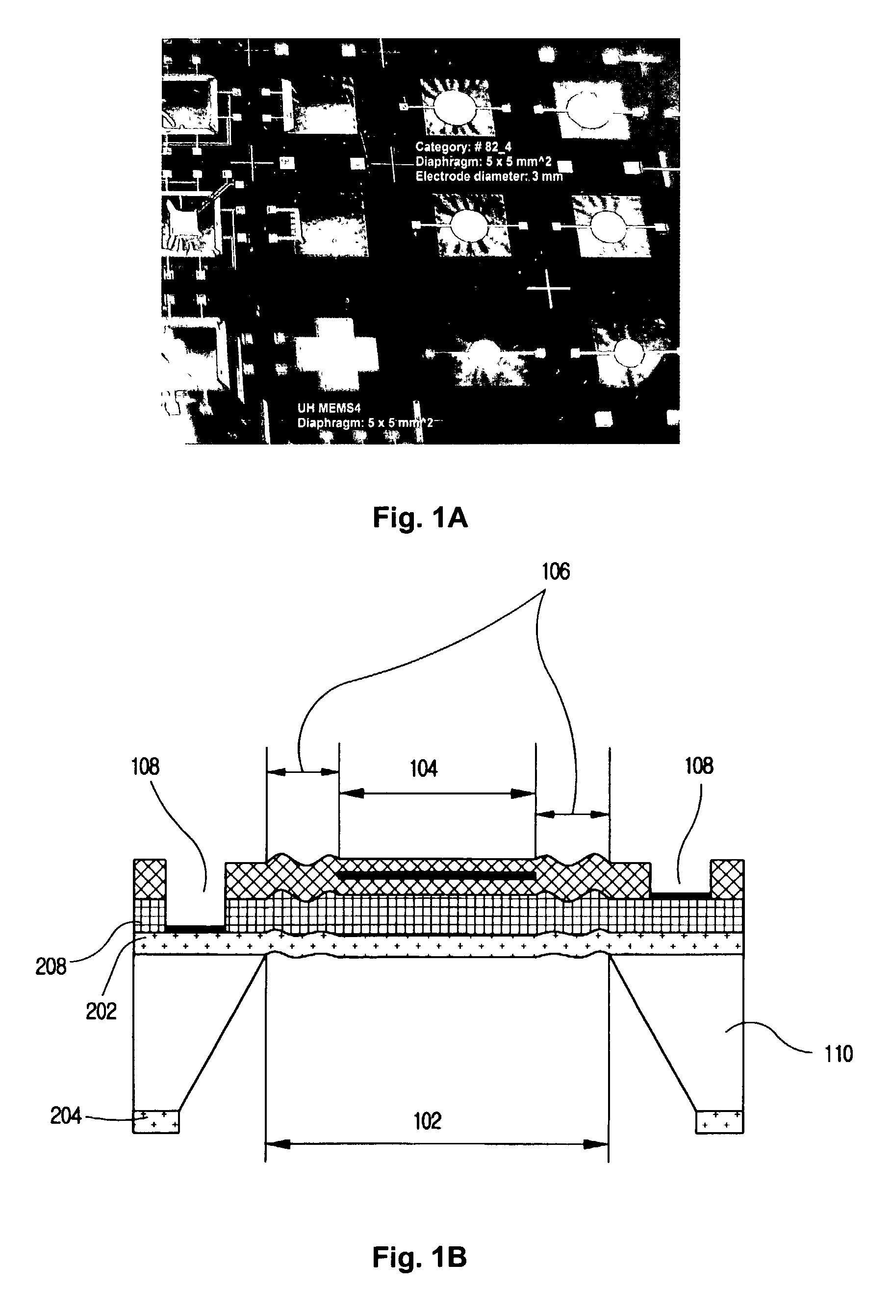
[0011]The key to this breakthrough is the usage of a diaphragm that has a very high compressive residual stress, high enough to cause the diaphragm to be wrinkled. And we maintain flatness in the speaker active area through a mild tensile stress in the electrode layers, though the non-active area is wrinkled. This way, we can produce a large diaphragm deflection (without being hindered by the diaphragm stretching effect) with good control over a flat, active area where the electromechanical transduction is happening.

Problems solved by technology

However, ceramic is so fragile that it is very difficult to make thin sheet and also it is not economical in terms of mass production with on-chip circuitry for signal conditioning.
However, micromachined acoustic transducers made by these conventional diaphragm materials suffer from a relatively low output pressure and sensitivity, which are mainly because of the high stiffness and low deflection of these diaphragm materials in case of transducers application.

Method used


Image

  • Micromachined piezoelectric microspeaker and fabricating method thereof
  • Micromachined piezoelectric microspeaker and fabricating method thereof
  • Micromachined piezoelectric microspeaker and fabricating method thereof

Examples


Embodiment Construction

[0020]Microelectromechanical Systems (MEMS) technology has been used to fabricate tiny microphones and microspeaker [1,2,3] on silicon wafer. This method of fabricating acoustic transducers on silicon wafer has the following advantages over the more traditional methods: potentially low cost due to the batch processing, possibility of integrating sensor and amplifier on a single chip, and size miniaturization.

[0021]Compared to more popular condenser-type MEMS transducers, piezoelectric MEMS transducers are simpler to fabricate, free from the polarization-voltage requirement, and responsive over a wider dynamic range [4,5,6]. However, piezoelectric MEMS transducer suffers from a relatively low sensitivity, mainly due to high stiffness of the diaphragm materials used for the transducer. The thin film materials for diaphragm strictly restricted to use such as silicon nitride, silicon, and polysilicon though these materials have high stiffness and residual stress. It is because of the co...


PUM

PropertyMeasurementUnit
diameteraaaaaaaaaa
diameteraaaaaaaaaa
diameteraaaaaaaaaa

Abstract

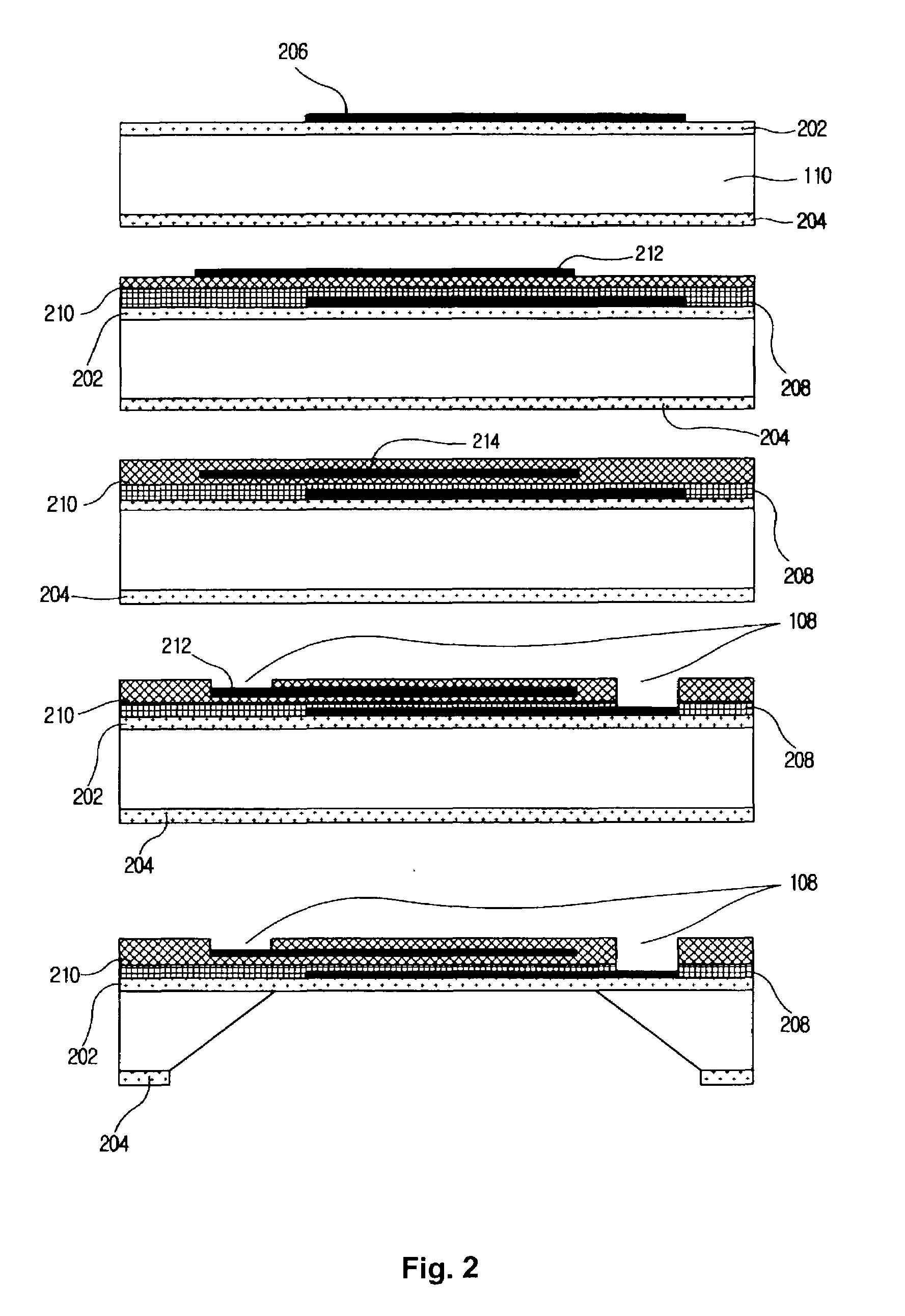
A micromachined piezoelectric microspeaker and its fabricating method are disclosed. The micromachined piezoelectric microspeaker comprises a diaphragm and a plurality of contact pads. The diaphragm comprises an active area which is flat, and a non-active area which is wrinkled and surrounds the active area. The plurality of contact pads for electrodes are located outside of the diaphragm and over a wafer. And, the method comprises the steps of forming a compressive film on a wafer, forming a bottom electrode on a predetermined part of the compressive film of the front side of the wafer, forming a piezoelectric film on the bottom electrode and on the compressive film of the front side of the wafer, forming a bottom insulator film on the piezoelectric film, forming a top electrode on a predetermined part of the bottom insulator where the top electrode is located over some part of the bottom electrode, forming a top insulator film on the top electrode and on the bottom insulator film, forming contact pads for the bottom electrode and top electrode at an outside part of each electrode, and removing a predetermined part of the wafer which is located between wafer parts located under the each contact pads.

Description

[0001]This application claims the benefit of U.S. Provisional Application No. 60 / 322,331, filed on Sep. 12, 2001.FIELD OF THE INVENTION[0002]This invention relates to the micromachined acoustic transducers and their fabrication technology. More particularly this invention relates to piezoelectric microspeaker with compressive nitride diaphragm.BACKGROUND OF THE INVENTION[0003]The prior art provides various examples of piezoelectric transducers. Examples of such piezoelectric transducers are disclosed in U.S. Pat. Nos. 6,140,740; 6,064,746; 5,956,292; 5,751,827; 5,633,552; 4,654,554, and 4,979,219. In many cases, the known piezoelectric vibrating plate comprises a single thin metal sheet on one or both sides of which is or are laminated a piezoelectric sheet or sheets consisting of a round thin piece of 20 to 30 mm in diameter. A conventional piezoelectric speaker has a construction in which a vibrating film or sheet is stretched on a frame while being applied tension and a plurality...

Claims


Application Information

Patent Timeline
Patent Type & Authority Patents(United States)
IPC IPC(8): H04R25/00H02N2/00H04R17/00
CPCH04R17/00Y10T29/4908Y10T29/49155Y10T29/42Y10T29/49005Y10T29/49147
Inventor YI, SEUNG-HWANKIM, EUN-SOK
Owner YI SEUNG HWAN
Why Eureka
Try Eureka