System and method for temperature sensing and monitoring

a temperature sensing and monitoring system technology, applied in the field of environmental control monitoring, can solve the problems of inability to achieve multiple sensor applications with rtds, inability to accurately detect temperature, and inability to accurately measure temperature, etc., to achieve the effect of enhancing the efficiency of industrial applications and without costly calibration procedures

Inactive Publication Date: 2006-02-28
ACROLON TECH
View PDF38 Cites 31 Cited by
  • Summary
  • Abstract
  • Description
  • Claims
  • Application Information

AI Technical Summary

Benefits of technology

[0013]These and other needs are addressed by the present invention in which an approach for digitally measuring temperature and other environmental parameters in support of a monitoring application is provided. Multiple probes, according to one embodiment, are deployed for sensing environmental parameters (e.g., temperature, liquid level, flow) within a tank that stores liquid for an industrial application, such as winemaking. Each probe has a thermally conductive cylindrical housing containing one or more digital temperature sensors. In addition, one of the probes includes analog inputs (e.g., Brix probe, level sensor, and flow s

Problems solved by technology

However, these systems traditionally have required manually intensive processes and expensive inflexible equipment.
The use of RTDs in industrial temperature control applications presents the following problems or issues: (1) RTD interface circuitry must be calibrated for the attached RTD and interconnection components; (2) RTD temperature sensing is error prone in harsh environments; and (3) multiple sensor applications are impractical with RTDs due to wiring constraints and required circuit real estate.
The long wires used to make these connections introduce electrical resistance in series with the RTD, which causes a constant temperature offset

Method used


Image

  • System and method for temperature sensing and monitoring
  • System and method for temperature sensing and monitoring
  • System and method for temperature sensing and monitoring

Examples


Embodiment Construction

[0031]A system, method, and software for performing temperature sensing and monitoring environmental parameters are described. In the following description, for the purposes of explanation, numerous specific details are set forth in order to provide a thorough understanding of the present invention. It is apparent, however, to one skilled in the art that the present invention may be practiced without these specific details or with an equivalent arrangement. In other instances, well-known structures and devices are shown in block diagram form in order to avoid unnecessarily obscuring the present invention.

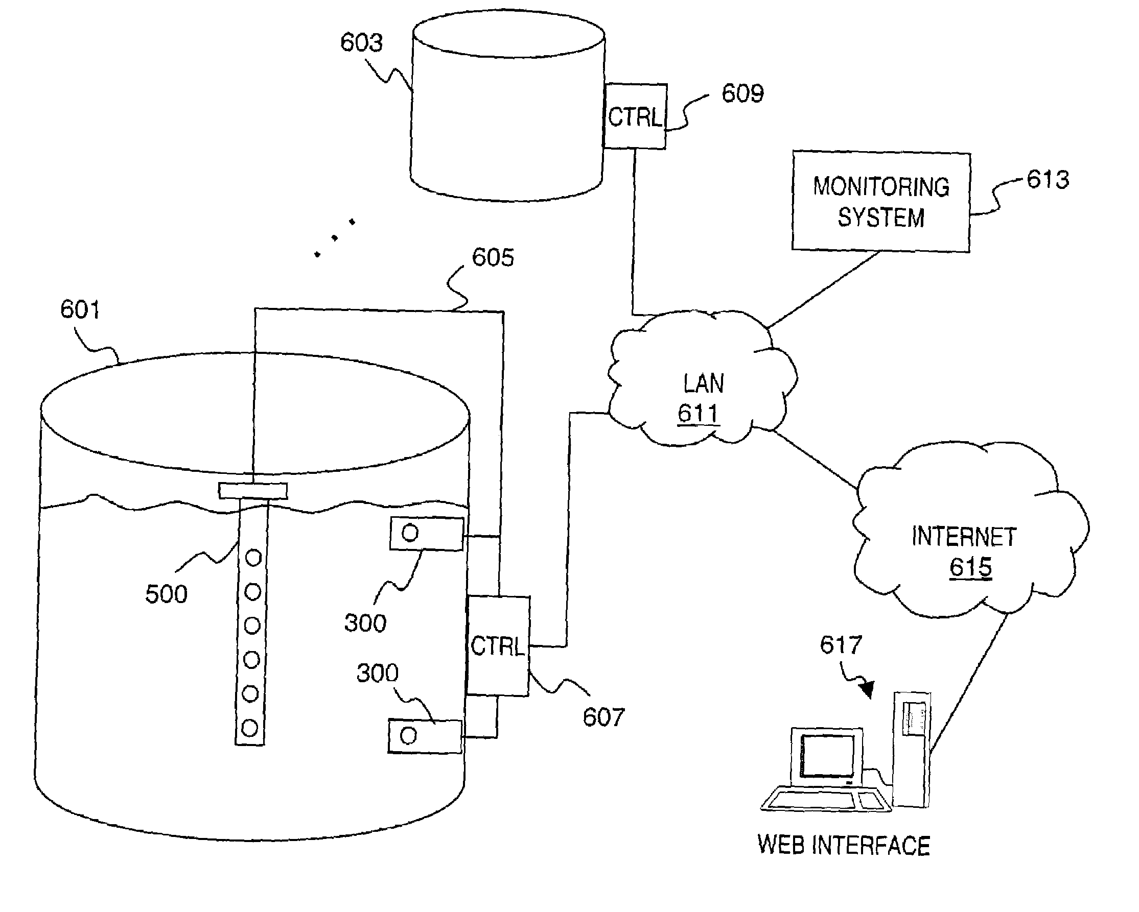
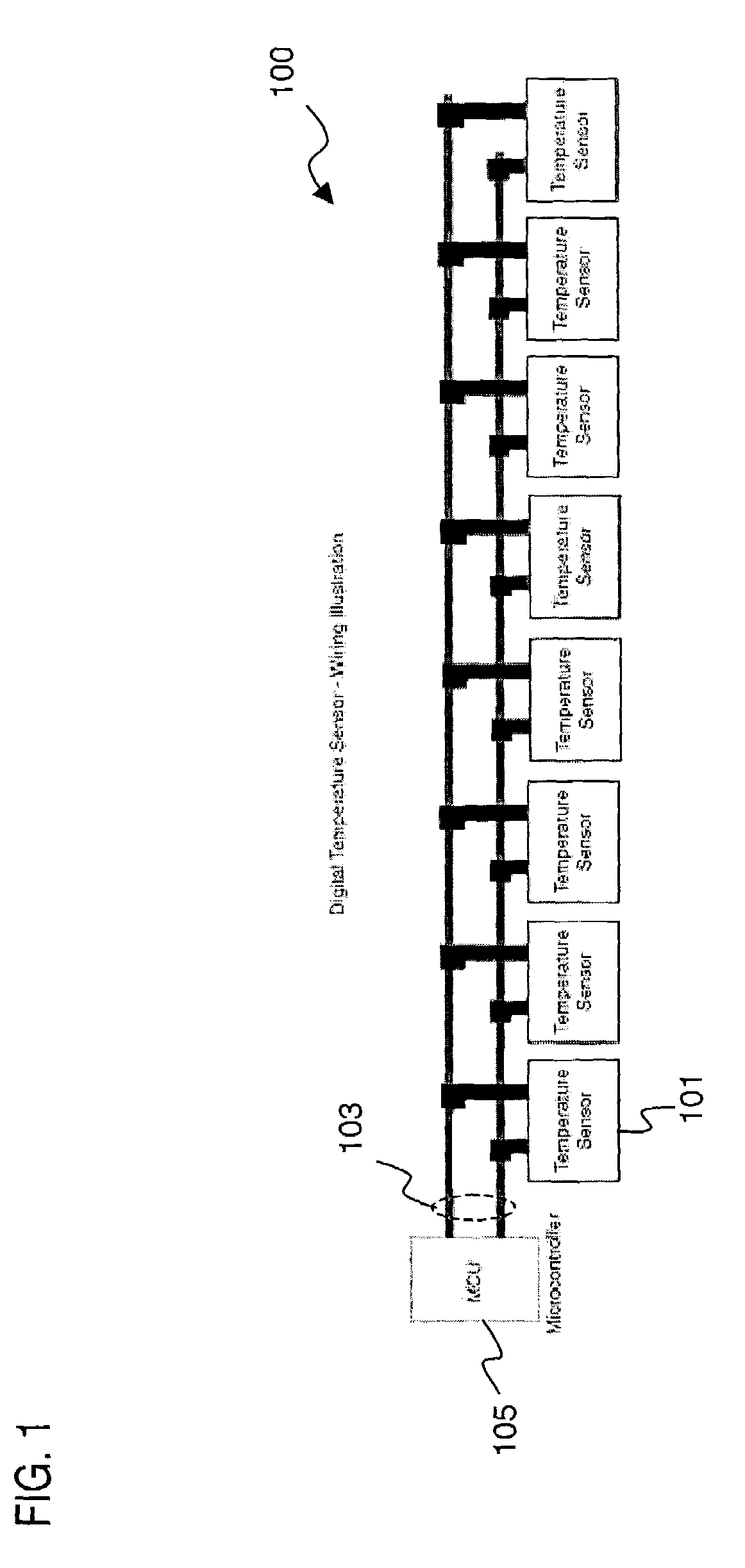
[0032]FIG. 1 is a diagram of a digital temperature sensing system, according to an embodiment of the present invention. As shown, a digital temperature sensing system 100, in an exemplary embodiment, is adapted for industrial temperature control applications, such as winemaking. The system 100 includes multiple digital temperature sensors 101 coupled to a fixed-sized bus 103 (e.g., ...


PUM


Abstract

An approach for digitally measuring temperature in support of a monitoring application is disclosed. Multiple probes, according to one embodiment, are deployed for sensing environmental parameters (e.g., temperature, liquid level, flow). Each probe has a thermally conductive cylindrical housing containing one or more digital temperature sensors. In addition, one of the probes includes analog inputs (e.g., Brix probe, level sensor, and flow sensor). The probes share a common fixed size bus and communicates data from the sensors to a controller. Based upon the collected data, the controller can initiate, for example, a pump-over in a winemaking process. The controller can interface with a data network to a monitoring system configured to store and analysis the collected data. The monitoring system supports access of the stored data over a public data network, such as the global Internet.

Description

RELATED APPLICATIONS[0001]The present application is related to and claims the benefit of the earlier filing date of U.S. Provisional Patent Application (Ser. No. 60 / 381,795), filed on May 21, 2002 and entitled “A Digital Temperature Sensing System”; the contents of which are hereby incorporated by reference.FIELD OF THE INVENTION[0002]The present invention relates to environmental control monitoring, and more particularly, to a digital temperature sensing system.BACKGROUND OF THE INVENTION[0003]Environmental monitoring and control systems play a vital role in many industrial applications to ensure proper production and quality. However, these systems traditionally have required manually intensive processes and expensive inflexible equipment.[0004]For example, modern temperature control systems rely on Resistance Temperature Devices (RTDs) for sensing temperature. RTDs are wire wound and thin film devices that work on the physical principle of the temperature coefficient of electric...

Claims


Application Information

Patent Timeline
IPC IPC(8): G01K7/00G01K13/00G01K1/02
CPCG01K1/026
Inventor EGIDIO, PAUL B.
Owner ACROLON TECH
Why Eureka
Try Eureka