Charged particle beam extraction and formation apparatus

a technology of beam extraction and charge particle, applied in the direction of discharge tube luminescnet screen, non-electron-emitting shielding screen, etc., can solve the problems of limited range of operation, mechanical simplicity of the system, and grid erosion

Inactive Publication Date: 2006-02-28
VEECO INSTR
View PDF24 Cites 3 Cited by
  • Summary
  • Abstract
  • Description
  • Claims
  • Application Information

AI Technical Summary

Benefits of technology

[0028]In one embodiment, a grid mounting ring has a contact region and a hidden region, the hidden region formed by a recess or groove in the dielectric mounting ring. The hidden region has an aspect ratio of at least five (5) and preferably as much as ten (10). The mounting ring, contact region and hidden region is substantially circular. The mounting ring is a high temperature dielectric material.
[0029]In one embodiment, an electric contact in a holder has a high temperature spring bias for contact to a grid. The contact is molybdenum and the spring pro

Problems solved by technology

For comparison, one and two-grid systems are mechanically simpler but have a limited range of operation at low beam divergence and are subject to grid erosion.
Providing and maintaining these demanding tolerances is substantially complicated by thermal gradients which can exist between the center and periphery of the grids and also between the grid electrodes and grid support components.
Because these designs have multiple parts and tend to be somewhat complex, they usually require some manual grid alignment, at least for initial set-up.
However, grid stiffening rings are exposed to rapid thermal transitions.
Nonuniformity in the temperature distribution can lead to grid distortion with consequent aperture misalignment and beamlet vectoring, which can cause ion impingement on the accelerator and decelerator grids.
Finally, utilization of molybdenum stiffening rings appreciably increases the construction weigh

Method used


Image

  • Charged particle beam extraction and formation apparatus
  • Charged particle beam extraction and formation apparatus
  • Charged particle beam extraction and formation apparatus

Examples


Embodiment Construction

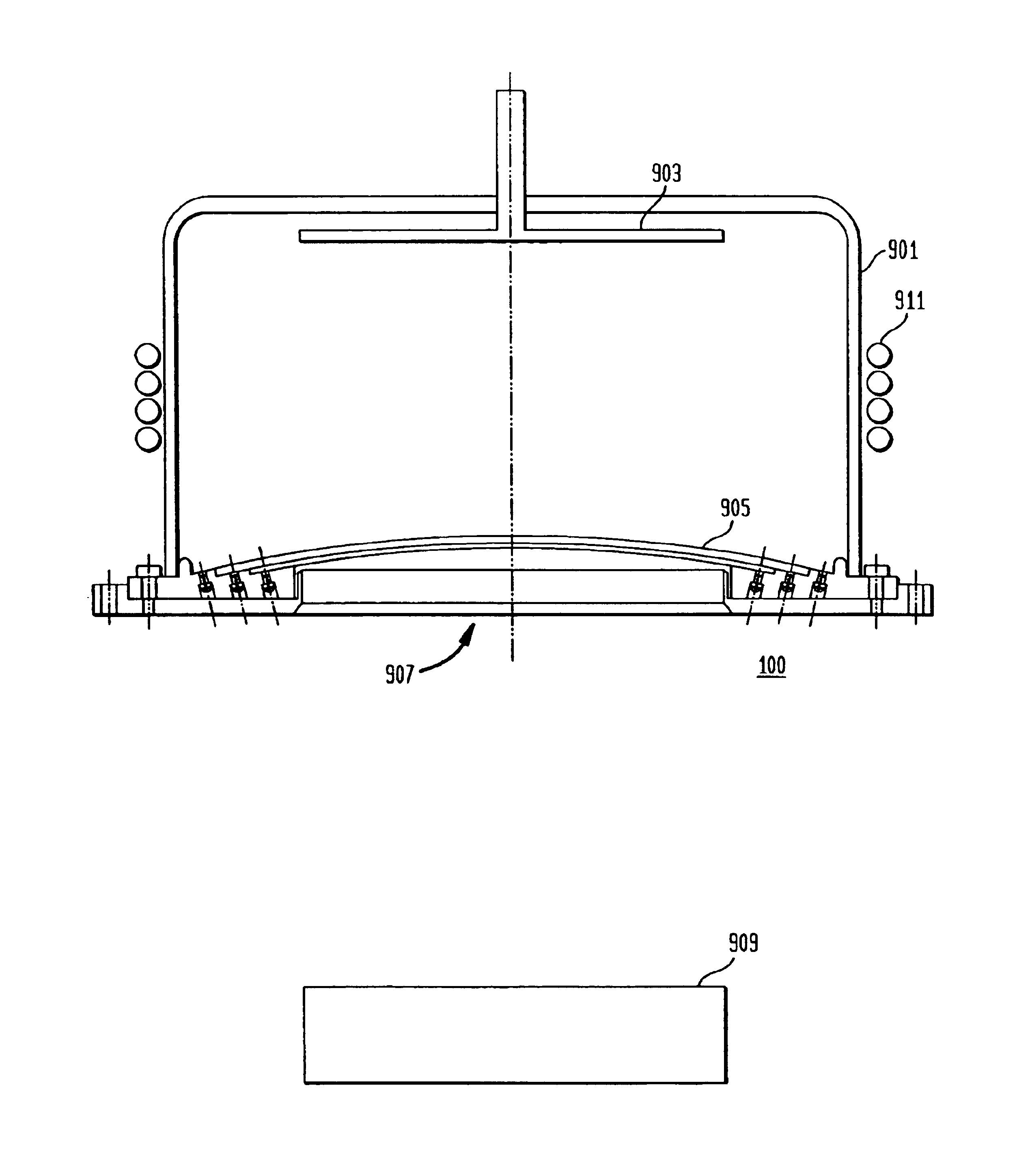
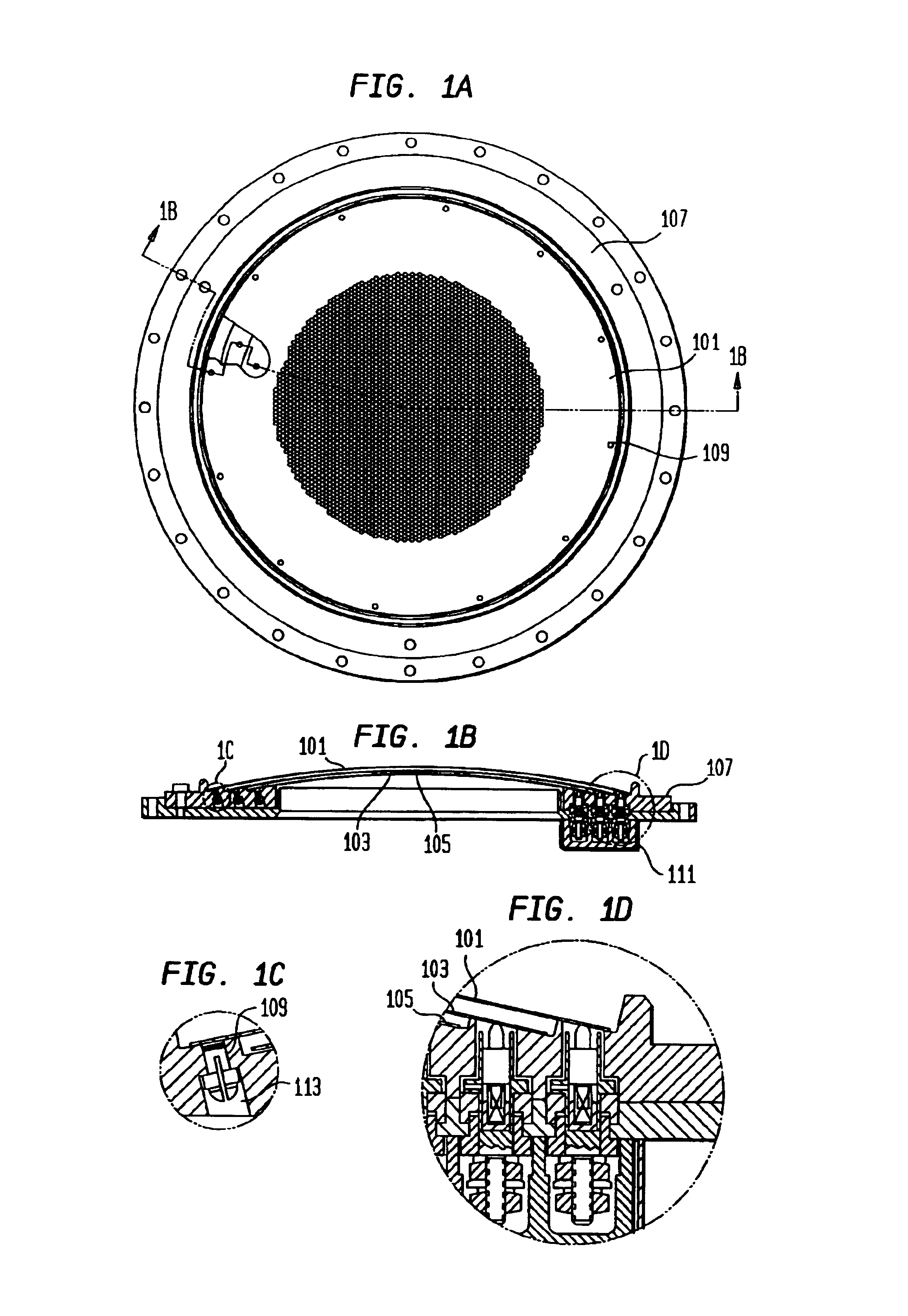
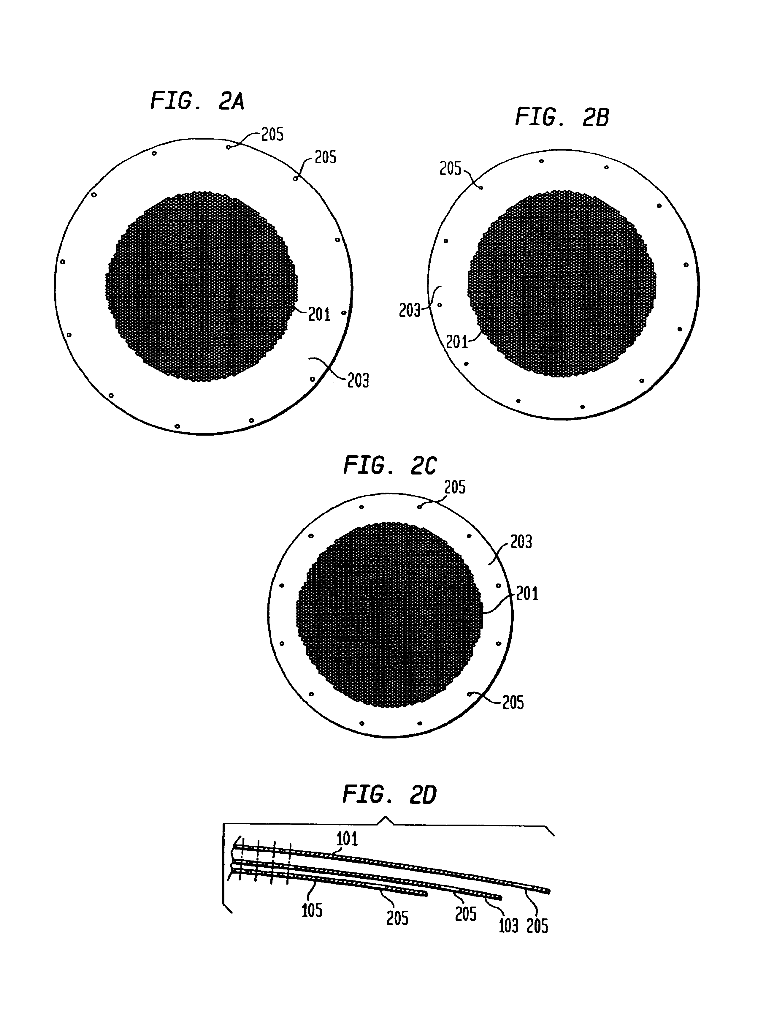
[0052]In the present invention, the above-mentioned objectives are provided by a “flangeless” grid mounting design, which has the following features:

[0053]In the dished grid optics assembly only the spherical dished portion of the grid electrodes are used, i.e. the mounting flange is removed after the dishing operation. Thus the problems of distortion and residual stresses in the peripheral flange area produced during dishing are reduced or eliminated. The absence of a flange portion on a dished grid also allows the grid to expand and contract with minimal stress.

[0054]In one aspect of the grid assembly design, the grid electrodes are all supported by a common mounting ring. The mounting ring is a single piece and is fabricated from a material with low thermal and electrical conductivity, such as ceramic or quartz. The single piece mounting ring substantially supports the grids along their entire perimeter. To provide for electrical isolation of the grid potentials under exposure to...


PUM


Abstract

A charged particle apparatus, with multiple electrically conducting semispheric grid electrodes, the grid electrodes mounted in a dielectric mounting ring, with hidden areas or regions to maintain electrical isolation between the grid electrodes as sputter deposits form on the grid electrodes and mounting ring. The grid electrodes are mounted to the mounting ring with slots and fastening pins that allow sliding thermal expansion and contraction between the grid electrodes and mounting ring while substantially maintaining alignment of grid openings and spacing between the grid electrodes. Asymmetric fastening pins facilitate the sliding thermal expansion while restraining the grid electrodes. Electrical contactors supply and maintain electrical potentials of the grid electrodes with spring loaded sliding contacts, without substantially affecting the thermal characteristics of the grid electrodes.

Description

[0001]This is a divisional of Ser. No. 10 / 413,176 filed Apr. 14, 2003 now U.S. Pat. No. 6,774,550 which is a division of prior application Ser. No. 09 / 390,841, filed Sep. 7, 1999 which issued to U.S. Pat. No. 6,590,324, to which priority under 35 U.S.C. §120 is claimed.FIELD OF THE INVENTION[0002]The invention relates generally to the field of charged particle sources and more specifically to charged particle sources with grid electrode optics forming apertures for the charged particles.BACKGROUND OF THE INVENTION[0003]Gridded, broad-beam ion sources, first developed for ion propulsion engines for spacecraft, are used in a variety of applications, such as ion beam etching (IBE), ion beam sputter deposition (IBSD), materials modification, and nuclear fusion technology. Ions are usually extracted from a discharge plasma by multi-grid ion optics. The plasma generator and the ion optics assembly are the two major components of the broad-beam ion source.[0004]The plasma is usually genera...

Claims


Application Information

Patent Timeline
IPC IPC(8): H01J17/04H01J27/02
CPCH01J27/022H01J27/024H01J37/3053H01J37/08H01J2237/3151H01J2237/061
Inventor KANAROV, VIKTORHAYES, ALAN V.YEVTUKHOV, RUSTAMYAKOVLEVITCH, DANIEL
Owner VEECO INSTR
Why Eureka
Try Eureka