Color liquid crystal display devices

a liquid crystal display and liquid crystal technology, applied in the field of color liquid crystal display devices, can solve the problems of affecting the expansion of affecting the color reproduction range of liquid crystal display elements, and increasing the absorption in the principal emission regions, so as to improve the chromatic purities of both green and red

Inactive Publication Date: 2006-02-28
MITSUBISHI CHEM CORP
View PDF12 Cites 52 Cited by
  • Summary
  • Abstract
  • Description
  • Claims
  • Application Information

AI Technical Summary

Benefits of technology

[0031]Namely, the present inventors have conducted intensive studies and found that, by optimizing the spectral curve of the color filter, particularly the spectral transmittance of the green pixels and the emission spectrum of the backlight, so as to satisfy the above conditions (1) to (3), it became feasible to reproduce deep green and thereby readily achieve the color liquid crystal display device with the NTSC percentage of at least 80% or even at least 90%, thus accomplishing the present invention.
[0032]The above condition (1) indicates that in the green wavelength region (from 500 to 530 nm), the emission intensity from the green pixel is high and it is possible to achieve the chromaticity coordinates (0.21, 0.71) of the green among the three primary colors in the NTSC system.
[0051]In the second invention, by satisfying the above condition (5), it becomes feasible to provide the red pixel with higher brightness and with high purity, capable of efficiently transmitting the emission from the red phosphor with high chromatic purity. Furthermore, by satisfying the above condition (6), it becomes feasible to efficiently cut the sub-emission at the wavelength of 585 nm from a Tb type phosphor usually used as a green phosphor and to enhance the chromatic purity of the red pixel more.
[0052]The second invention involves optimization of the spectral curve of the red pixel of the color filter and the emission spectrum of the backlight on the basis of certain rules, whereby it is feasible to provide the red pixel with high chromatic purity, without sacrificing the brightness of the image, and, in turn, to readily achieve the expansion of the color reproduction range of the color liquid crystal display device.
[0054]By satisfying the above condition (7), it becomes feasible to transmit the emission from the red phosphor more efficiently and provide the red pixel with higher brightness and with high purity, without damaging the chromatic purity of the red pixel achieved by the above conditions (5) and (6).

Problems solved by technology

However, the backlight using the aforementioned phosphors shows emissions in the other wavelength regions than red, green and blue, as sub-emissions as shown in FIG. 2, and these can be the cause of degrading the chromatic purity.
Namely, these sub-emissions impede the expansion of the color reproduction range of the liquid crystal display elements.
However, the pigments originally have the characteristic of the spectral curve being not sharp, and thus the use of the large amount of pigments posed the problem that absorption also increased in the principal emission regions and the resultant image became dark as a whole.
There were also the following problems: an increase of the pigment concentration in each pixel of the color filter degraded the performance as a photolithographic material, e.g., it resulted in increase of development time; it became difficult to control the pattern shape; the yield decreased; and so on.
Furthermore, an increase of thickness of the color filter tended to cause trouble more readily in production steps of a liquid crystal panel and, in turn, led to an increase of production cost of the liquid crystal display device.
However, this method is not preferable because of its complex steps and increase of production cost as a result.
Furthermore, it is virtually impossible to achieve reproduction with ultrahigh chromatic purity of NTSC percentage of at least 95%, by the conventional backlights using the aforementioned cold-cathode tube.
In order to achieve the NTSC percentage of at least 80%, it is essential to improve the backlight, but it is not sufficient.
However, for example, if there is a change in the green emission wavelengths of the backlight, the balance will be lost between those in the green pixels of the same color filter.
For these reasons, the simple improvement in the emission wavelengths of the backlight cannot achieve the ultrahigh chromatic purity of NTSC percentage of at least 80% or even at least 90%, while the conventional color filter is used as it is.
On the other hand, the problem of sub-emission is also prominent about the red pixels.
It is, however, impossible to achieve the adequate contrast in this wavelength region by the presently, industrially available colorants such as pigments and dyes.
As a result, in order to obtain the red pixels with high chromatic purity, the pigment had to be used in large quantity with an inevitable sacrifice of brightness.
However, a further shift of the red pixels toward red will result in darkening images.
Furthermore, with the backlight made from the conventionally used red phosphor having the emission peak near 610 nm, the purity of red was not sufficient and it was difficult to reproduce adequately deep red images.

Method used


Image

  • Color liquid crystal display devices
  • Color liquid crystal display devices
  • Color liquid crystal display devices

Examples


preparation example 1

Preparation of Backlight ①

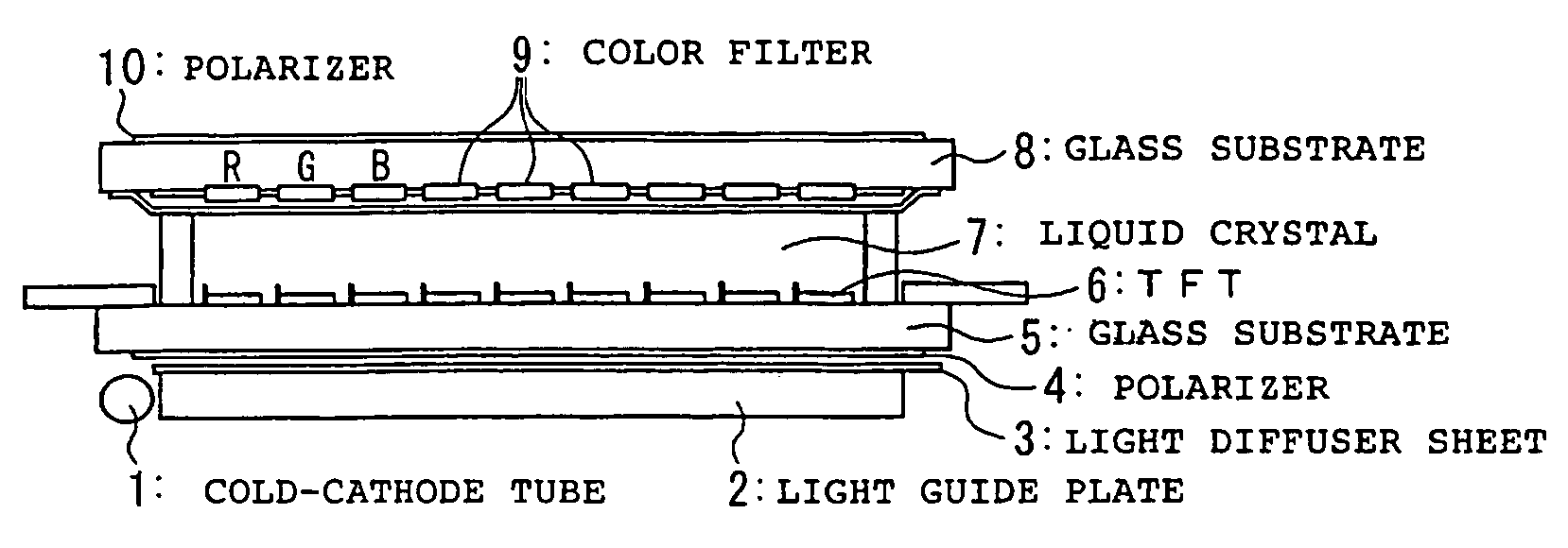
[0213]A phosphor slurry was prepared by thoroughly mixing 52 parts of Y2O3:Eu (trade name “LP-RE1” manufactured by KASEI OPTONIX, LTD.) as a red phosphor, 18 parts of BaMgAl10O17:Eu,Mn (trade name “LP-G3” manufactured by KASEI OPTONIX, LTD.) in the composition of Ba09Eu0.1O(Mg0.79Mn0.21)O.5Al2O3 as a green phosphor, and 30 parts of BaMgAl10O17:Eu (trade name “LP-B4” manufactured by KASEI OPTONIX, LTD.) as a blue phosphor with butyl acetate and nitrocellulose lacquer, applied and dried on an internal surface of a glass tube with a tube diameter of 2.3 mm, and then baked at 620° C. for five minutes. Thereafter, a cold-cathode tube for a backlight was fabricated by the ordinary procedure of attachment of electrodes, evacuation, Hg and gas introduction, sealing, and so on.

[0214]Then a cyclic polyolefin type resin sheet (trade name “ZEONOR” manufactured by ZEON CORPORATION) of wedge shape, which had the size of 289.6×216.8 mm and thicknesses varying along the di...

preparation example 2

Preparation of Backlight ②

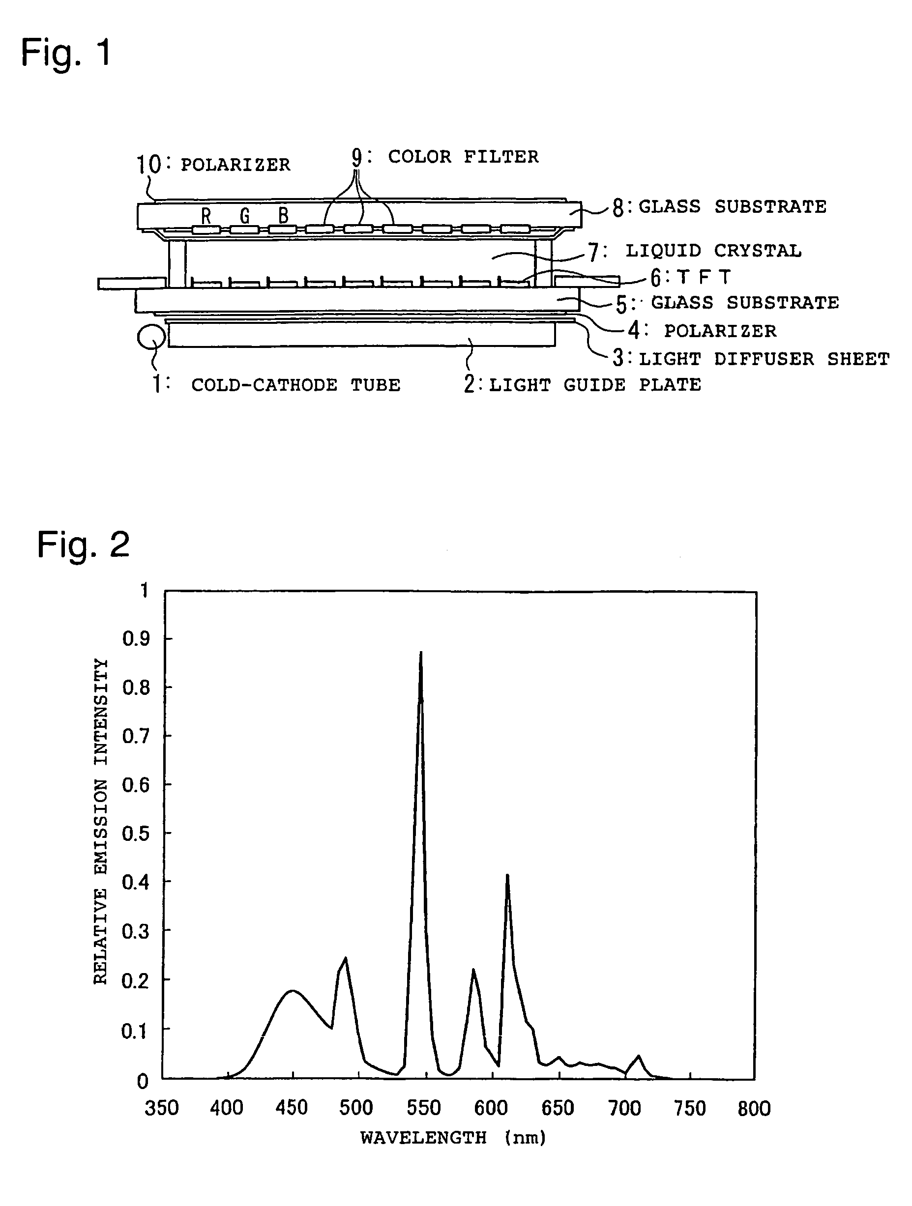
[0219]A cold-cathode tube for a backlight was fabricated in the same manner as in Preparation Example 1 except for use of 40 parts by weight of a YVO4:Eu3+ type phosphor (trade name “MGV-620” manufactured by KASEI OPTONIX, LTD.) as a red phosphor, 22 parts by weight of a LaPO4:Ce,Tb phosphor (trade name “LP-G2” manufactured by KASEI OPTONIX, LTD.) as a green phosphor, and 38 parts by weight of BaMgAl10O17:Eu (trade name “LP-B4” manufactured by KASEI OPTONIX, LTD.) as a blue phosphor, and a. backlight ② was prepared therefrom in the same manner as in Preparation Example 1. A relative emission spectrum of the backlight thus obtained is presented in FIG. 6.

[0220]This backlight ② had the principal emission wavelengths of red: about 620 nm, blue: about 450 nm and green: about 545 nm.

preparation example 3

Preparation of Backlight ③

[0221]A cold-cathode tube for a backlight was fabricated in the same manner as in Preparation Example 1 except for use of 40 parts by weight of a YVO4:Eu3+ type phosphor (trade name “MGV-620” manufactured by KASEI OPTONIX, LTD.) as a red phosphor, 22 parts by weight of BaMgAl10O17:Eu,Mn (trade name “LP-G3” manufactured by KASEI OPTONIX, LTD.) in the composition of Ba0.9Eu0.1O.(Mg0.79Mn0.21)O.5Al2O3 as a green phosphor, and 38 parts by weight of BaMgAl10O17:Eu (trade name “LP-B4” manufactured by KASEI OPTONIX, LTD.) as a blue phosphor, and a backlight ③ was prepared therefrom in the same manner as in Preparation Example 1. A relative emission spectrum of the backlight thus obtained is presented in FIG. 7.

[0222]This backlight ③ had the principal emission wavelengths of red: about 620 nm, blue: about 450 nm and green: about 515 nm.


PUM

PropertyMeasurementUnit
wavelengthaaaaaaaaaa
wavelength regionaaaaaaaaaa

Abstract

The invention relates to a color liquid crystal display device with a combination of light shutters that utilize a liquid crystal, a color filter having color elements of at least three colors of red, green and blue corresponding to the light shutters, and a backlight for transmission illumination.

Description

[0001]This application is a continuation of PCT / JP03 / 11085, filed on Aug. 29, 2003, which claims priority to JP 2002-254705, filed on Aug. 30, 2002, and JP 2002-307300, filed on Oct. 22, 2002.TECHNICAL FIELD[0002]The first invention of the present application relates to a color liquid crystal display device and, particularly, to a color liquid crystal display device comprising a combination of light shutters utilizing a liquid crystal, a color filter having color elements of at least three colors of red, green and blue corresponding to the light shutters, and a backlight for transmission illumination, wherein emission wavelengths of the backlight are improved and wherein the transmittance of the color filter, particularly the spectral transmittance of green pixels of the color filter, is adjusted corresponding to the emission wavelengths of the backlight, so as to realize the green pixels with high chromatic purity and thereby accomplish reproduction of a deep green image, thereby a...

Claims


Application Information

Patent Timeline
Patent Type & Authority Patents(United States)
IPC IPC(8): G02F1/13357G02B5/20G02F1/1335
CPCG02B5/201G02B6/0036G02B6/0038G02F1/133514G02F1/133615G02B6/004G02F2001/133607G02F1/133607G02B6/0001G02F1/1335
Inventor KAWANA, SHINSAKO, NAOKIKIJIMA, NAOTOHISAMUNE, TAKAYUKIOOTSUKA, REIJI
Owner MITSUBISHI CHEM CORP
Why Eureka
Try Eureka