Analog signal separator for UWB versus narrowband signals

a technology of analog signal and narrowband, applied in the field of radio frequency communication receivers, can solve the problems of reducing reception quality, degrading the reception of intended signals, and unsuitable techniques, and achieve the effect of preventing amplifier saturation and expanding the apparent dynamic range of amplifiers

Inactive Publication Date: 2006-02-28
NORTH STAR INNOVATIONS
View PDF27 Cites 41 Cited by
  • Summary
  • Abstract
  • Description
  • Claims
  • Application Information

AI Technical Summary

Benefits of technology

[0027]While several embodiments are disclosed herein, one embodiment would be to include one or more stub circuits in the receiver front end arranged to pass the UWB signal, but cancel an RFI signal. Another embodiment would be to include one or more sub-circuits that include a splitter, one path delayed relative to the other, and one path possibly inverted relative to the other, and the two paths combined in a summer. Another embodiment would include a same sub-circuit, but with an adaptive delay for adapting the null frequency to cancel observed RFI. In order to extend the apparent dynamic range of an amplifier, in another embodiment the stub can be located at a distance away (e.g. to reflect a short circuit at the notch frequency) from the amplifier so as to prevent the amplifier from saturating.

Problems solved by technology

A problem arises if an unintended signal, particularly a strong signal, is coupled into the antenna at the same time as the desired signal.
In this case, the unintended signal, if in the frequency spectrum that coincides with the intended signal, will tend to “jam” the radio, thereby reducing reception quality.
Furthermore, even if the unintended signal is not coincident in frequency with the desired signal, the unintended signal may nonetheless drive a low noise amplifier, which is typically coupled to the antenna, into a saturation mode.
Both effects degrade the reception of the intended signal.
However, such techniques are not suitable if the intended signal is relatively wideband, because the interfering signal has spectra within the spectra of the desired signal.
However, the problem arises that the RFI may be so high that the difference in magnitudes between the RFI and the desired signal is beyond the dynamic range of the receiver circuitry.
However, such systems usually require a detector to distinguish an interferer from an intended signal and special cancellation circuitry dedicated to the function of “notching” the unintended RFI.
Inserting notch filters into the passband creates not only detrimental insertion loss, therefore increasing the noise for the radio front end, but also introduces phase distortion (and corresponding time sidelobes) into the received signal thus limiting the effectiveness of such systems.
Furthermore, lower cost systems are usually not adaptive because it is difficult to adjust the center band of the notch frequencies based on the particular interfering signal at any given time.
The RFI is suppressed because the RFI does not coherently combine on a chip-by-chip basis with the spreading code (i.e. it is mostly uncorrelated to the desired signal).
However, a problem with this approach is that the notch filter 12 destroys part of the desired signal and will increase the noise effect by having a predetermined amount of insertion loss and will “notch” a certain predetermined amount of signal energy in the excised band.
As can be seen, there are a number of large narrowband interference sources that would give rise to in-band, or even out-of-band radio front-end saturation problems.
The challenge, as presently recognized, is to correctly distinguish an intended, transmitted signal at the UWB receiver in the presence of narrowband tones that interfere with the intended signal, while not adversely altering the nature of the intended UWB signal.

Method used


Image

  • Analog signal separator for UWB versus narrowband signals
  • Analog signal separator for UWB versus narrowband signals
  • Analog signal separator for UWB versus narrowband signals

Examples


Embodiment Construction

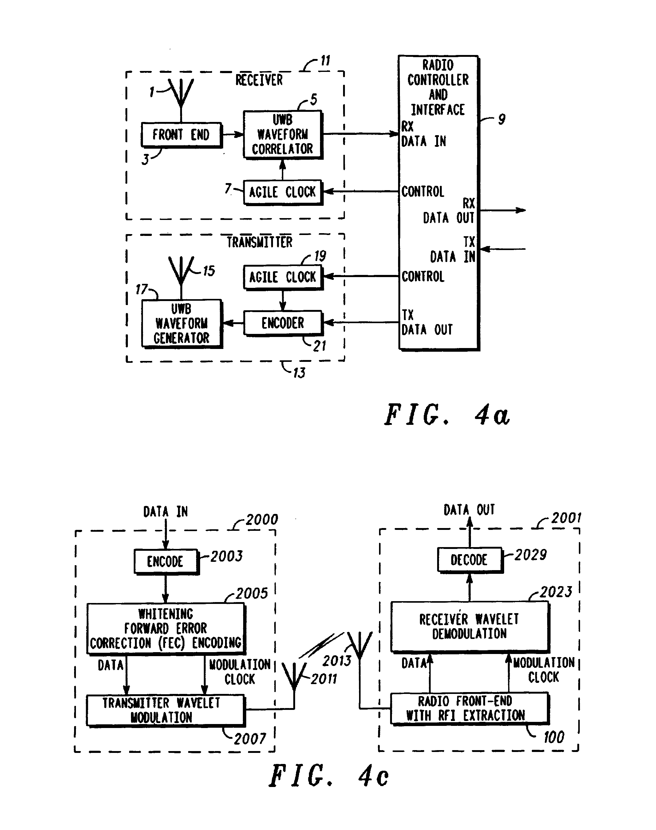
[0049]Referring now to the drawings, FIG. 4a is a block diagram of an ultra-wide band (UWB) transceiver. In FIG. 4a, the transceiver includes three major components, namely, receiver 11, radio controller and interface 9, and transmitter 13. Alternatively, the system may be implemented as a separate receiver 11 and radio controller and interface 9, and a separate transmitter 13 and radio controller and interface 9. The radio controller and interface 9 serves as a media access control (MAC) interface between the UWB wireless communication functions implemented by the receiver 11 and transmitter 13 and applications that use the UWB communications channel for exchanging data with remote devices.

[0050]The receiver 11 includes an antenna 1 that converts a UWB electromagnetic waveform into an electrical signal (or optical signal) for subsequent processing. The UWB signal is generated with a sequence of shape-modulated wavelets, where the occurrence times of the shape-modulated wavelets may...


PUM

PropertyMeasurementUnit
impedanceaaaaaaaaaa
impedanceaaaaaaaaaa
output impedanceaaaaaaaaaa

Abstract

A system, method, and computer program product for removing “narrowband” interference from a broader spectrum containing a UWB signal, in a receiver of the UWB signal. The RFI is extracted from a broader spectrum to remove interference from the UWB signal, by employing an impulse response in a radio front-end of the UWB receiver that is matched with an incoming wavelet employed as part of a UWB signal to be received, matching the impulse response to the wavelet and its time-shifted and inverted versions, passing the wavelet unscathed through the receiver, and excising narrowband signals (continuous tones). Exemplary embodiments for the RFI extraction mechanism include a transmission line circuit, an active transmission line circuit, and an adaptable, controllable phase delay circuit.

Description

CROSS REFRERENCE TO RELATED PATENT DOCUMENTS[0001]The present document contains subject matter related to that disclosed in commonly owned, co-pending application Ser. No. 09 / 209,460 filed Dec. 11, 1998, entitled ULTRA WIDE BANDWIDTH SPREAD-SPECTRUM COMMUNICATIONS SYSTEM; Ser. No. 09 / 633,815 filed Aug. 7, 2000, entitled ELECTRICALLY SMALL PLANAR UWB ANTENNA; application Ser. No. 09 / 563,292 filed May 3, 2000, entitled PLANAR ULTRA WIDE BAND ANTENNA WITH INTEGRATED ELECTRONICS; application Ser. No. 60 / 207,225 filed May 26, 2000, entitled ULTRA WIDEBAND COMMUNICATION SYSTEM AND METHOD; Application Ser. No. 60 / 238,466, filed Oct. 10, 2000, entitled ULTRA WIDE BANDWIDTH NOISE CANCELLATION MECHANISM AND METHOD; Application Ser. No. 60 / 217,099 filed Jul. 10, 2000, entitled MULTIMEDIA WIRELESS PERSONAL AREA NETWORK (WPAN) PHYSICAL LAYER SYSTEM AND METHOD; application Ser. No. 09 / 685,203, filed Oct. 10, 2000, entitled SYSTEM AND METHOD FOR BASEBAND REMOVAL OF NARROWBAND INTERFERENCE IN ULTRA...

Claims


Application Information

Patent Timeline
Patent Type & Authority Patents(United States)
IPC IPC(8): H04B1/713H04B7/212H04L25/49H04N5/21B60C19/12B29B7/18B29K21/00C08J3/20C08J3/205C08K5/33C09J121/00C09J123/16C09K3/10H04B1/7163H04B1/719
CPCH04M3/42034H04B1/719H04B1/71637H04B1/1036
Inventor MCCORKLE, JOHN W.
Owner NORTH STAR INNOVATIONS
Why Eureka
Try Eureka