Method and apparatus for detecting electro-magnetic reflection from biological tissue

a biological tissue and electromagnetic reflection technology, applied in the field of biological tissue system and method for locating anatomical structures, can solve the problems of delayed placement of intravenous lines, high morbidity associated with multiple venipunctures, and often the rate-limiting step of intravenous compounds, and achieve high contrast

Inactive Publication Date: 2006-02-28
THE BOARD OF TRUSTEES OF THE UNIV OF ARKANSAS
View PDF20 Cites 50 Cited by
  • Summary
  • Abstract
  • Description
  • Claims
  • Application Information

AI Technical Summary

Benefits of technology

[0009]Yet another object of the present invention is to provide a method and apparatus for producing a clear three-dimensional image of an anatomical structure by detecting the electromagnetic radiation characteristics reflected from the target area.
[0011]Still another object of the present invention is to provide helmet mounted imaging technology in a single integral helmet which allows the wearer to view an anatomical structure located within a patient such that the image is continuously oriented according to the orientation of the helmet wearer's head.
[0012]Yet another object of the present invention is to provide a method and apparatus for quickly, accurately and efficiently allowing for the performance of venipuncture.
[0013]Another object of the present invention is to provide a method and apparatus for improving contrast between any anatomical structure and its surrounding tissue for use in any imaging system.

Problems solved by technology

Venipuncture, which is often the rate-limiting step when administering intravenous compounds, can take as long as a half hour with a typical patient or longer when the patient is a neonate, infant, geriatric, obese or burn patient.
Notwithstanding the enormous financial burden on our society as a whole because operating rooms and health-care providers must wait as an intravenous line is placed, the delay in placing an intravenous line can in fact be life threatening.
Furthermore, there is a high morbidity associated with multiple venipunctures caused by the clinician's failure to locate the vessel.
The reason venipuncture is sometimes difficult to do is that the blood vessels are often located relatively deep within the tissue which, because of its absorptive and scattering optical properties, makes visualization of the blood vessel impossible under normal conditions.
Furthermore, the situation is made worse by the fact that the vessel may spasm and constrict if it is manipulated too much.
Furthermore, reducing the time of the procedure limits the providers' exposure to a potentially contaminated needle.
The transilluminator has essentially fallen into disuse because it fails to provide enough contrast between the blood vessel and tissue to be of use other than for venipuncture of superficial vessels.
Furthermore, some versions of the blood-vessel transilluminator caused thermal damage to the patient.
These references, however, did not disclose efficient means of eliminating detection of scattered light from areas outside the vessel region (i.e., off angle light).
Nor did they disclose the elimination of detection of polychromatic white noise, such as from ambient room light or from a polychromatic light source.
Later devices only employed a subtraction technique using expensive digital processing and cumbersome computer analysis to eliminate unwanted scattered waves.
Furthermore, these devices did not disclose a method of noise reduction for use with a white light source, but rather relied on use of a monochromatic laser light source to reduce polychromatic noise.
Such an arrangement unfortunately does not allow for convenient same-side illuminating and detecting such as in the form of a single unit goggle or scanning device.
Accordingly, manipulation of many of these devices along with the patient required multiple clinical personnel.

Method used


Image

  • Method and apparatus for detecting electro-magnetic reflection from biological tissue
  • Method and apparatus for detecting electro-magnetic reflection from biological tissue
  • Method and apparatus for detecting electro-magnetic reflection from biological tissue

Examples


Embodiment Construction

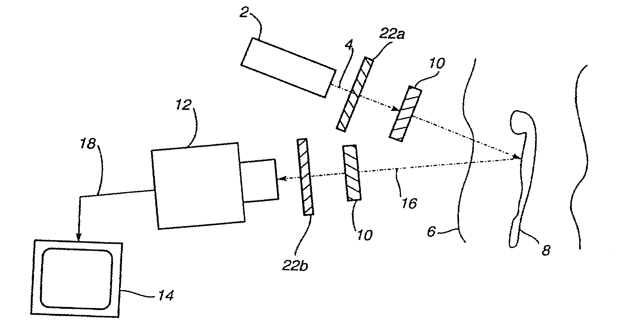
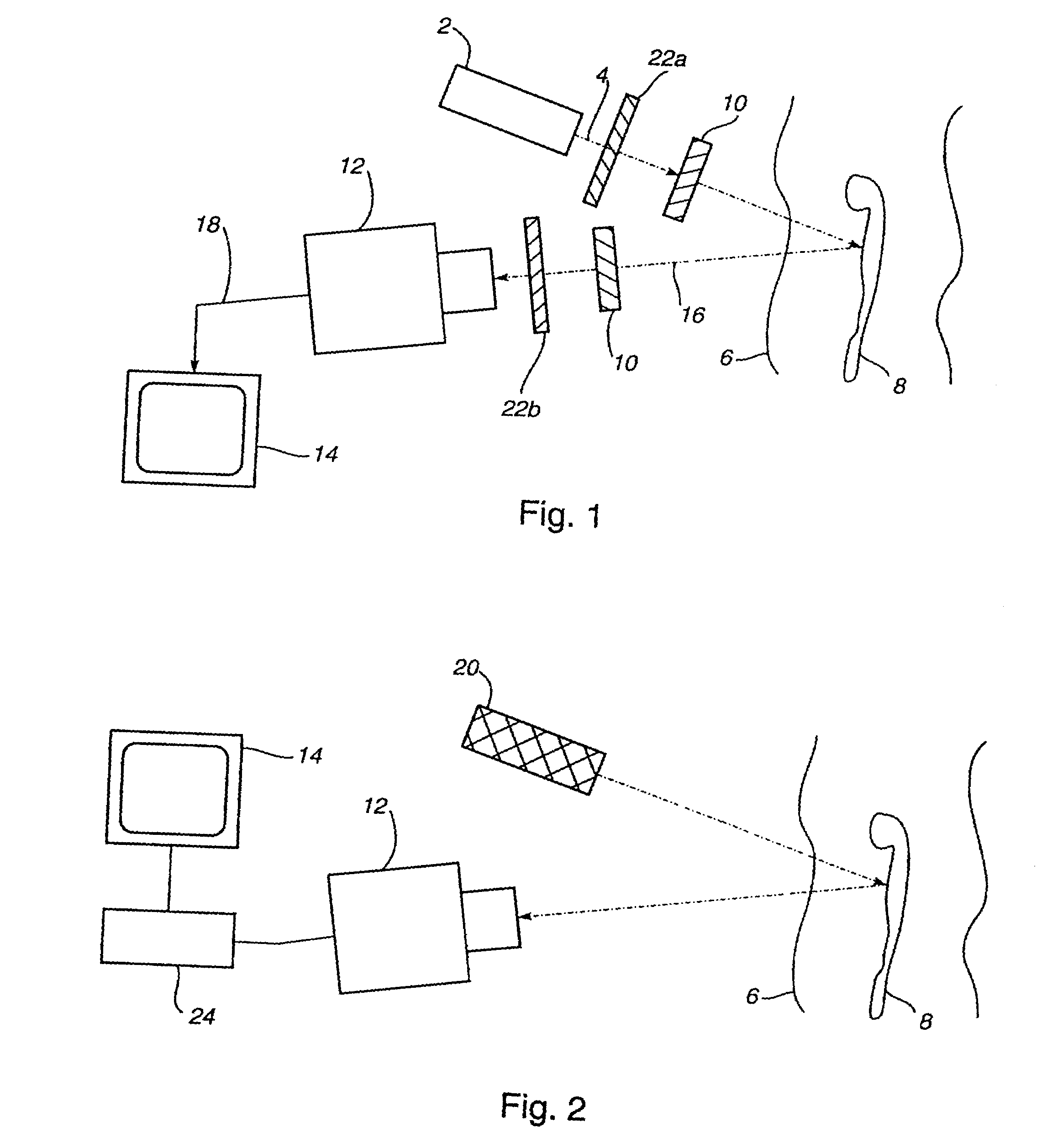
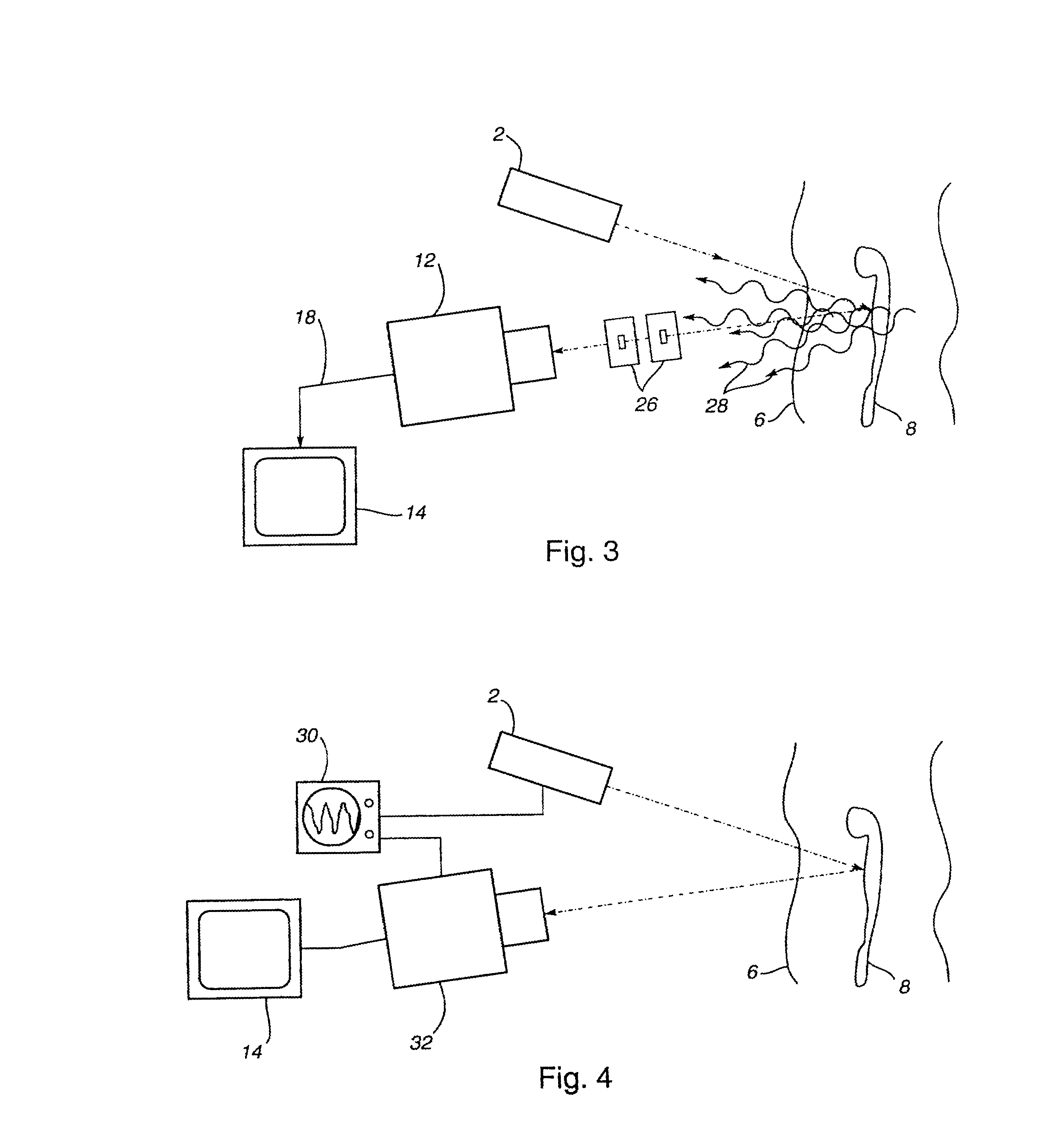
[0020]The present invention provides a system for locating an anatomical structure, such as a blood vessel, wherein the system comprises a light source and an image detector, which detects light radiation reflected from the area of examination, and a monitor which receives and displays image information from said image detector. The term “light source” includes but is not limited to polychromatic sources, such as white light sources, as well as monochromatic sources such as laser light sources. The term “image detector” refers to any device capable of detecting light, including but not limited to charge-coupled device infrared cameras (CCD's), video cameras, and liquid crystal television detectors.

[0021]Optionally, the present invention may include elements that enhance the contrast between the anatomical structure and the surrounding tissue in the image. The term “contrast enhancing element” refers to any element or combination of elements which enhance contrast between the anatomi...


PUM

PropertyMeasurementUnit
wavelengthaaaaaaaaaa
wavelengthsaaaaaaaaaa

Abstract

A system and method is provided to view an anatomical structure such as a blood vessel in high contrast with its surrounding tissue. The system and method may be used to produce an image of an anatomical structure using reflected electromagnetic radiation singularly scattered from target tissue. The system and method may also provide same-side illumination and detection of reflected electromagnetic radiation in a convenient integral imaging device. The system and method may also provide helmet mounted imaging technology in a single integral helmet which allows the wearer to view an anatomical structure located within a patient such that the image is continuously oriented according to the orientation of the helmet wearer's head. The system and method may also be used in the performance of venipuncture. The system and method may provide for improved contrast between any anatomical structure and its surrounding tissue for use in any imaging system.

Description

CLAIM OF PRIORITY[0001]This case is a Continuation of U.S. application Ser. No. 09 / 479,755, filed on Jan. 7, 2000, now U.S. Pat. No. 6,272,374, which is a Continuation of U.S. application Ser. No. 08 / 483,480, filed on Jun. 7, 1995, now U.S. Pat. No. 6,032,070.BACKGROUND OF THE INVENTION[0002]The present invention relates to a system and method for locating anatomical structures within biological tissue. More particularly, the invention relates to a system and method for locating anatomical structures such as blood vessels in a mammalian body by utilizing equipment sensitive to the unique absorption and scattering characteristics of the target structure, such as blood. Further, the present invention provides a system and method to enhance the contrast between a target structure, such as a blood vessel, and its surrounding tissue.[0003]Every day in the United States, many hundreds-of-thousands of medical procedures involving the puncturing of blood vessels are performed. Venipuncture,...

Claims


Application Information

Patent Timeline
Patent Type & Authority Patents(United States)
IPC IPC(8): A61B1/04A61B5/103A61B5/00G01N21/17A61B5/145A61B10/00A61B17/34A61B19/00
CPCA61B5/0059A61B5/489A61B19/52A61B5/1405A61B5/15003A61B5/150748A61B17/3403A61B2019/5206A61B2019/5231A61B2019/262A61M5/427A61B2090/502A61B90/36A61B2090/373A61B2090/306
Inventor FLOCK, STEPHEN T.FINK, LOUISWANER, MILTON
Owner THE BOARD OF TRUSTEES OF THE UNIV OF ARKANSAS
Why Eureka
Try Eureka