
Oxygen-based biomass combustion system and method

a biomass combustion and oxygen-based technology, applied in the direction of solid fuel combustion, combustion types, lighting and heating apparatuses, etc., can solve the problems of reducing the quantity of carbon monoxide and vocs produced, the energy required to move gas in the combustor and ancillary, etc., and achieving the effect of minimizing the heat loss of heating unnecessary vocs

Inactive Publication Date: 2006-03-07
MUNIZ CESAR A
View PDF36 Cites 21 Cited by
  • Summary
  • Abstract
  • Description
  • Claims
  • Application Information

AI Technical Summary

Benefits of technology

[0006]According to the present invention, firebelts ensure that the heat loss from heating unnecessary oxidant is minimized. The quantity of oxygen at each point in the combustion process is closely controlled. This oxygen control benefits the combustion process in three ways:
[0007]First, by minimizing the heat loss of the combustion process, this minimizes the amount of carbon monoxide and volatile organic carbons (VOC) that are produced. Carbon monoxide and VOC, priority pollutants, are produced indirectly proportional to the combustion temperature. Therefore, by maximizing the combustion temperature, the quantity of carbon monoxide and VOCs produced are minimized.
[0009]Thirdly, by minimizing the amount of air supplied to the combustion process, the amount of energy required to move gas in the combustor and ancillary is minimized. Electrical energy costs are typically 20–50% less than similar combustion systems where the air is used.
[0011]Firstly, the heat is reflected to a point where the heat can be used to assist the combustion process. This is generally where the fuel first enters the combustion process. At this point, the fuel must be heated and the water removed. These processes require addition of energy that can be added for heat of the combustion of a part of the fuel or from the reflected energy. Using a part of the fuel to preheat the remaining fuel is inefficient, leaving less total heat available for production of electricity. Using reflected heat removes or minimizes this inefficiency. The second way this benefits the overall combustion process is in that the energy is transferred in a beneficial way—not wasted by irradiating and heating the combustion chamber. Heat that is absorbed by the combustion chamber shell is generally wasted since there is no direct benefit from this radiation. A small portion is used in the maintenance of the necessary combustion temperature but the majority of irradiating heat is wasted as low-level heat irradiating from the combustor exterior. Reflective heat added to the fuel will benefit the overall combustion efficiency, and this is a feature of the present invention
[0012]Another feature of the invention is that the speed of the conveyor drive and the rate of inlet oxidant and diluent addition and the control of those gases is much more closely controlled so as to achieve high efficiency. Still another feature of the invention is that the fuel feed ramping is based on thermal conditions at the boiler output.

Problems solved by technology

First, by minimizing the heat loss of the combustion process, this minimizes the amount of carbon monoxide and volatile organic carbons (VOC) that are produced. Carbon monoxide and VOC, priority pollutants, are produced indirectly proportional to the combustion temperature. Therefore, by maximizing the combustion temperature, the quantity of carbon monoxide and VOCs produced are minimized.
Secondly, nitrogen oxides, another priority pollutant, is produced by combining the nitrogen in the air with the oxygen. This combination of nitrogen and oxygen only occurs at high temperatures and when nitrogen is present. The higher the temperature and the greater the nitrogen content of the gases, the greater the quantity of nitrogen oxides that are produced. While the combustor of the present invention utilizes high temperatures, the formation of nitrogen oxides is eliminated since there is no nitrogen in the oxidant and diluent to combine with the oxygen. All the oxygen is used in the combustion process.
Thirdly, by minimizing the amount of air supplied to the combustion process, the amount of energy required to move gas in the combustor and ancillary is minimized. Electrical energy costs are typically 20–50% less than similar combustion systems where the air is used.

Method used


Image

  • Oxygen-based biomass combustion system and method
  • Oxygen-based biomass combustion system and method
  • Oxygen-based biomass combustion system and method

Examples


Embodiment Construction

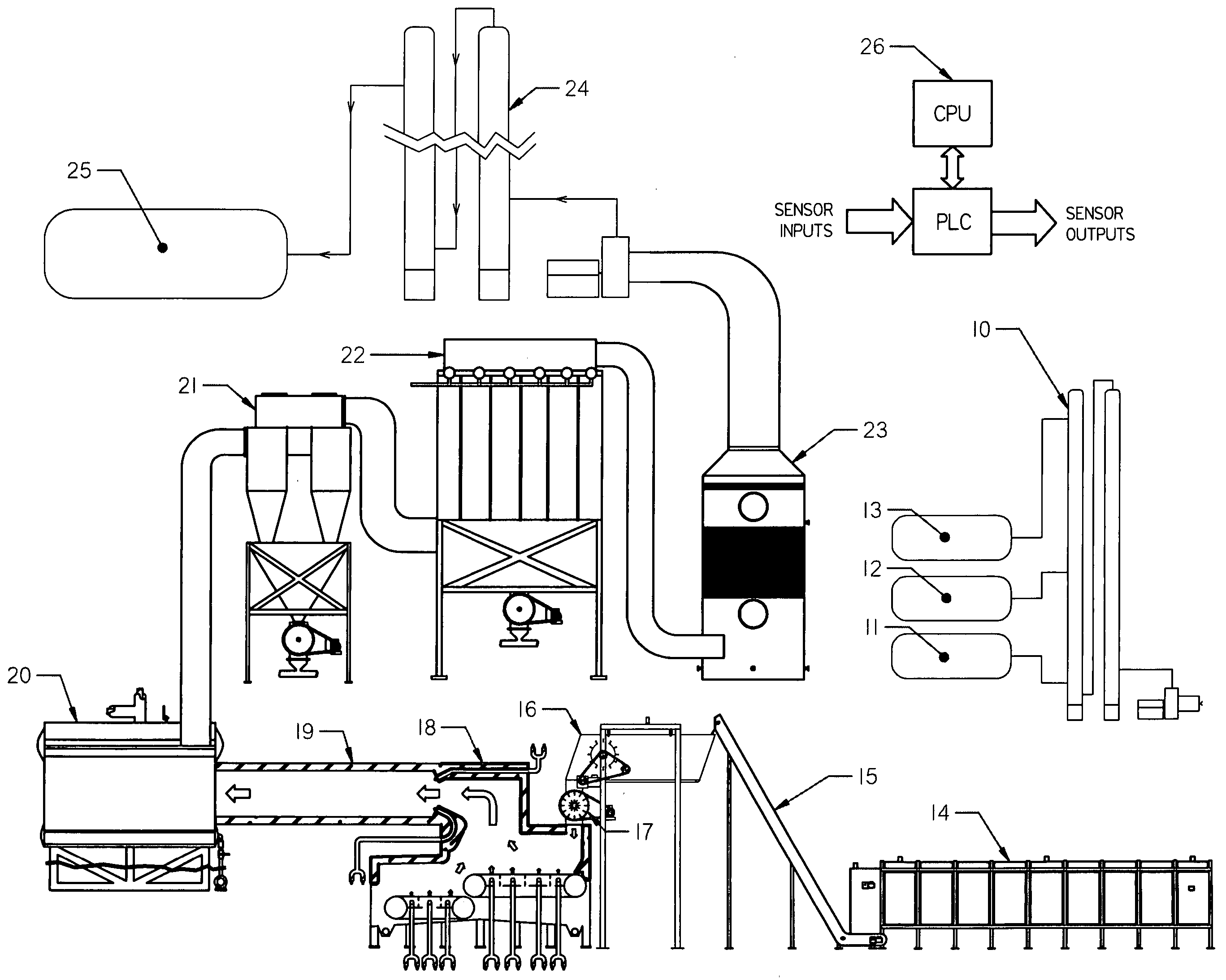
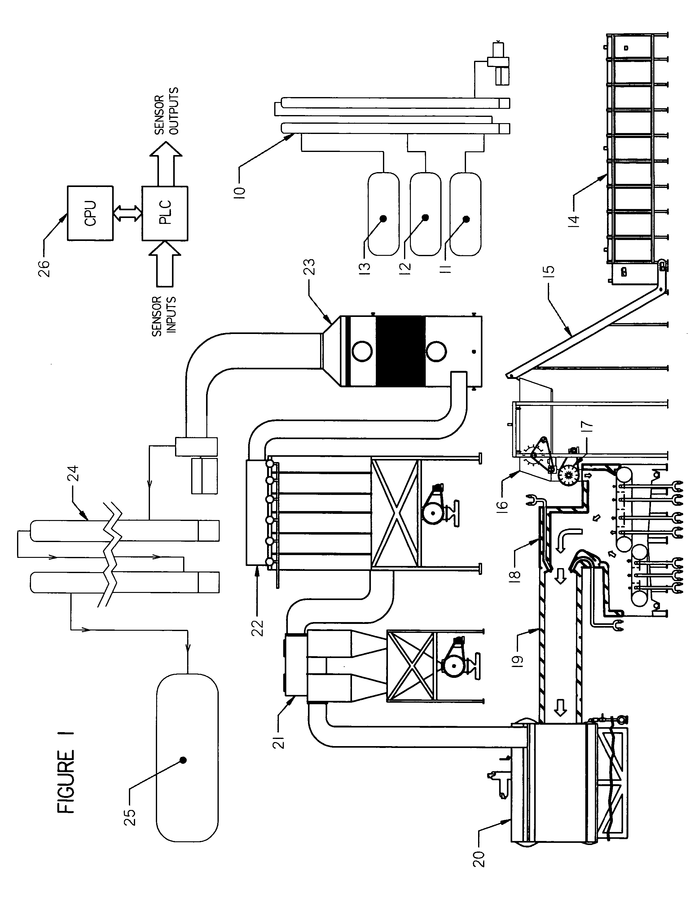
[0026]Referring now to FIG. 1, the gasifier system comprises an air separator unit 10, gas storage for oxygen 11, nitrogen 12, argon 13, a solid fuel storage unit 14 and fuel transport conveyor 15, inlet feed conveyor 16 and fuel metering unit 17, a gasifier 18, a gasifier firetube with connection to boiler 19, the boiler itself 20, a cyclone 21, baghouse 22, acid gas scrubber 23, carbon dioxide scrubber 24, carbon dioxide storage system 25, and control system 26 which is diagrammatically illustrated in FIGS. 9A, 9B and 9C.

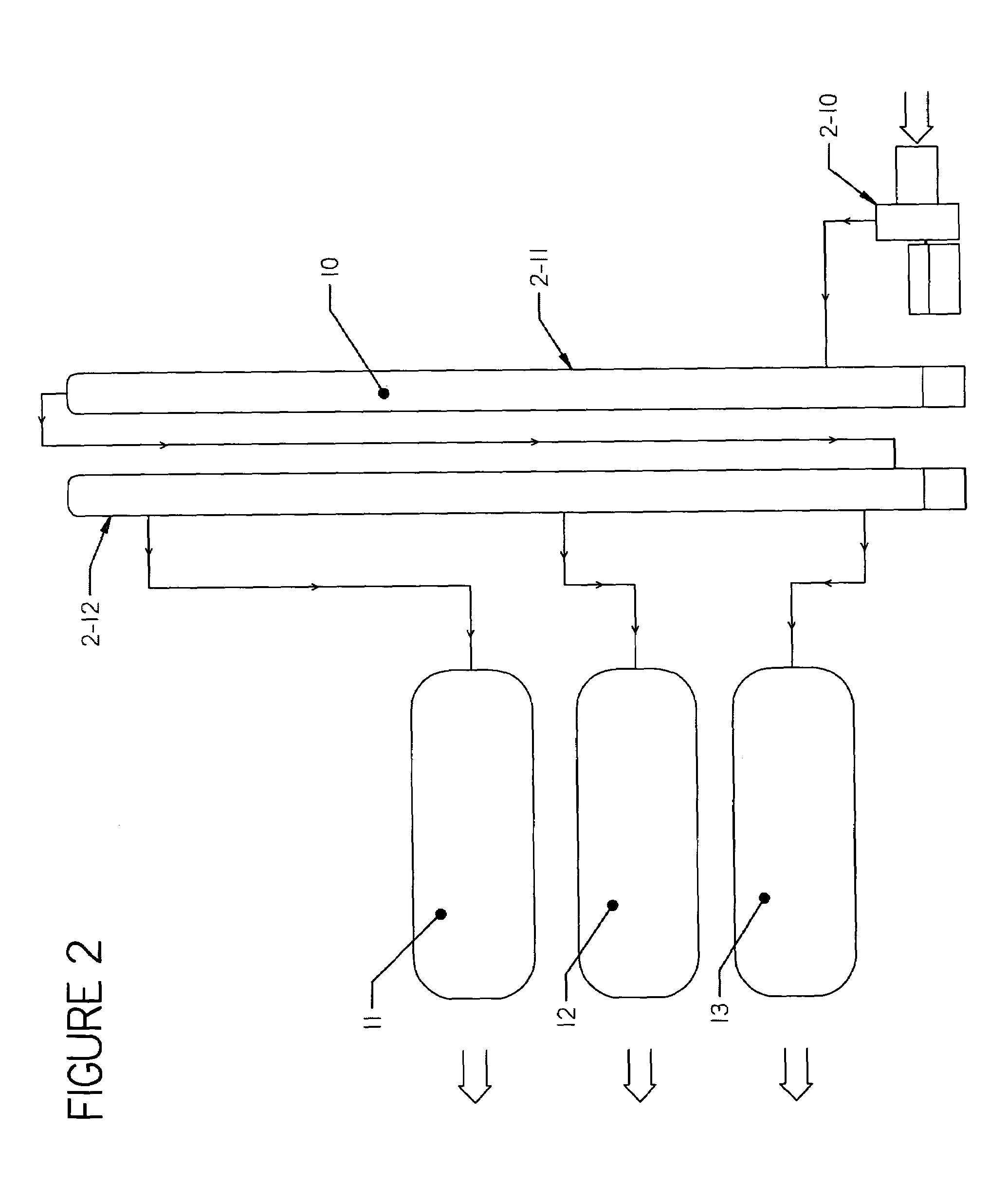
Air Separator Unit 10 (FIG. 2)

[0027]The air separator unit 10 separates air into its components parts; oxygen, nitrogen and argon. Trace gases normally present in air are vented. Gaseous air is compressed by a turbine compressor 2-10 and passes into condensing column 2-11 where the compressed gases are cooled and condensed into liquids. The liquids then pass into a fractionating tower 2-12 where they are heated and separated by their boiling points. The separated,...


PUM

PropertyMeasurementUnit
combustion temperatureaaaaaaaaaa
usable heat energyaaaaaaaaaa
lengthaaaaaaaaaa

Abstract

An oxygen-based biomass solid fuel combustion system and method has an air separator for separating oxygen from air providing a supply of oxygen for feeding oxygen to a solid fuel combustion chamber. An airlock feeds a metered amount of solid fuel to the solid fuel combustion chamber. A burner stage having a firetube for collecting fuel gases from the solid fuel combustion chamber combusts the collected fuel gases with further oxygen from the separator and heats a boiler to generate steam. A heat utilization device (e.g. an electrical generator) may be connected to the steam boiler. Nitrogen-free diluent gases (e.g. argon and carbon dioxide) are used to control combustion process temperatures. The usable heat energy and useful byproducts are extracted from the different stages of the process.

Description

REFERENCE TO RELATED APPLICATION[0001]The present application is the subject of provisional application No. 60 / 458,377 filed Mar. 31, 2003 entitled WASTE ENERGY SYSTEM WITH ZERO EMISSION. This application is also a continuation-in-part application of application Ser. No. 09 / 138,020 filed Aug. 21, 1998 entitled GASIFIER SYSTEM AND METHOD (now abandoned) and application Ser. No. 10 / 061,362 filed Feb. 4, 2002, now U.S. Pat. No. 6,532,879 and a continuation-in-part application of application Ser. No. 10 / 331,559 filed Dec. 31, 2002.BACKGROUND AND BRIEF DESCRIPTION OF THE INVENTION[0002]The present invention relates to a gasifier system and method for the efficient conversion of solid fuel waste materials (tires, etc.) and biomass materials into usable energy and useful products.DESCRIPTION OF THE PRIOR ART[0003]The prior art is best exemplified by U.S. Pat. No. 5,284,103 entitled BIO-MASS BURNER CONSTRUCTION by Hand et al, which is a division of U.S. Pat. No. 5,178,076 entitled BIO-MASS ...

Claims


Application Information

Patent Timeline
Patent Type & Authority Patents(United States)
IPC IPC(8): F23L7/00C10J1/00F23G5/00F23G5/027F23G5/16F23G5/46F23G7/10F23J15/02F23J15/04
CPCF23G5/006F23G5/16F23G5/46F23G7/10F23J15/02F23J15/04F23L7/007F23G5/0276Y02E20/344F23G2201/40F23G2203/8016F23G2205/18F23G2206/203F23J2217/101F23J2217/40F23L2900/07001Y02E20/12Y02E20/322Y02E20/32Y02E20/34
Inventor ABRAMS, STAN E.CULVEY, BRIAN
Owner MUNIZ CESAR A
Learn More