Oxygen-based biomass combustion system and method

Inactive Publication Date: 2005-02-03
MUNIZ CESAR A
View PDF5 Cites 13 Cited by
  • Summary
  • Abstract
  • Description
  • Claims
  • Application Information

AI Technical Summary

Benefits of technology

According to the present invention, firebelts ensure that the heat loss from heating unnecessary oxidant is minimized. The quantity of

Problems solved by technology

Secondly, nitrogen oxides, another priority pollutant, is pr

Method used


Image

  • Oxygen-based biomass combustion system and method
  • Oxygen-based biomass combustion system and method
  • Oxygen-based biomass combustion system and method

Examples


Example

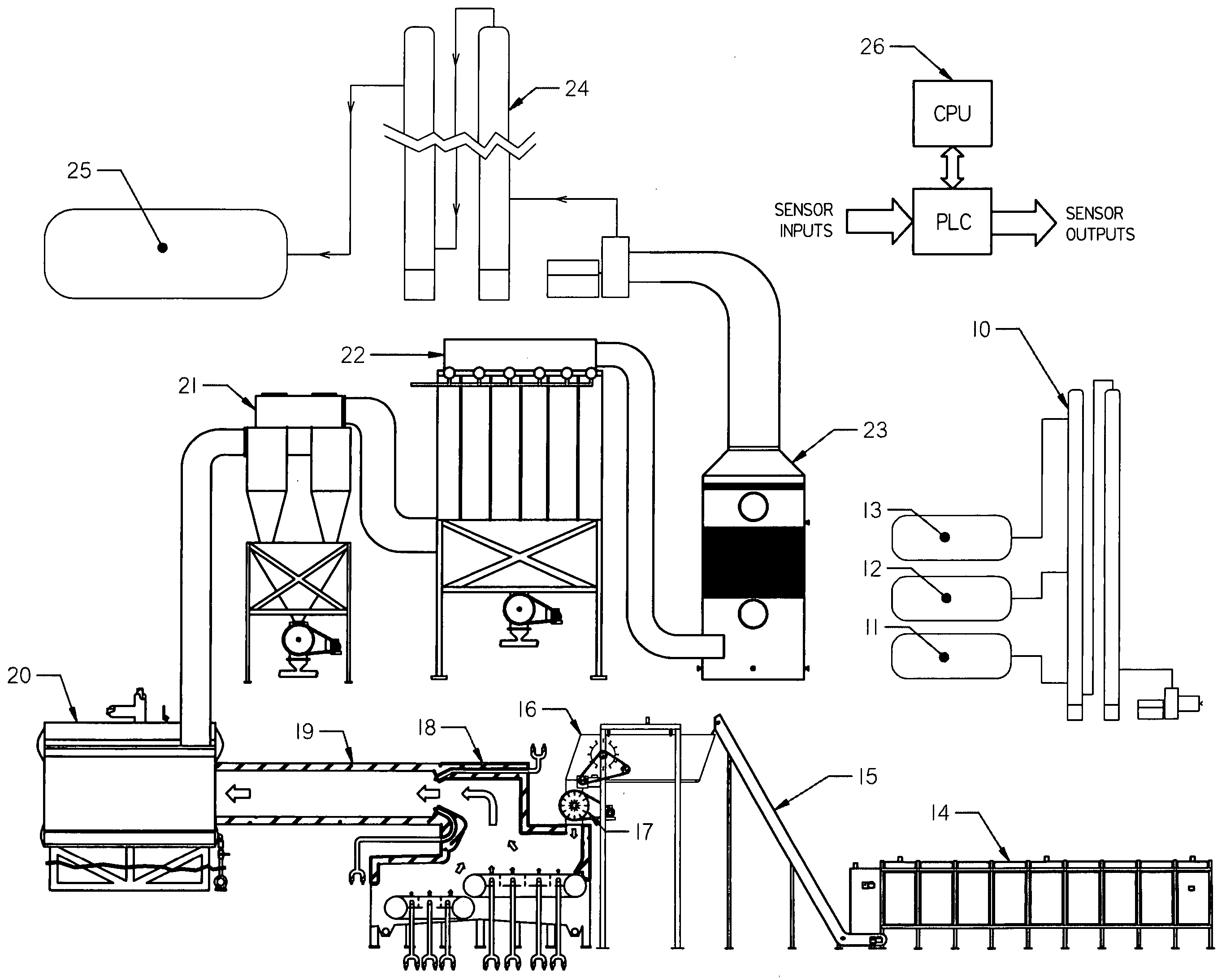
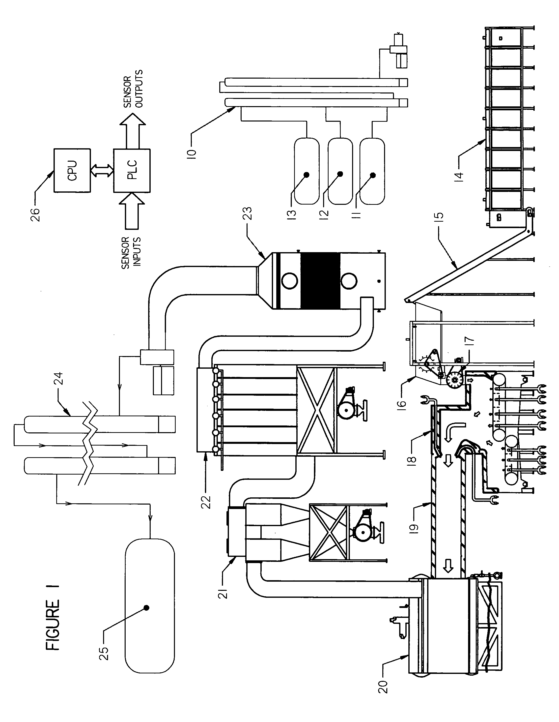
Referring now to FIG. 1, the gasifier system comprises an air separator unit 10, gas storage for oxygen 11, nitrogen 12, argon 13, a solid fuel storage unit 14 and fuel transport conveyor 15, inlet feed conveyor 16 and fuel metering unit 17, a gasifier 18, a gasifier firetube with connection to boiler 19, the boiler itself 20, a cyclone 21, baghouse 22, acid gas scrubber 23, carbon dioxide scrubber 24, carbon dioxide storage system 25, and control system 26 which is diagrammatically illustrated in FIGS. 9A, 9B and 9C.

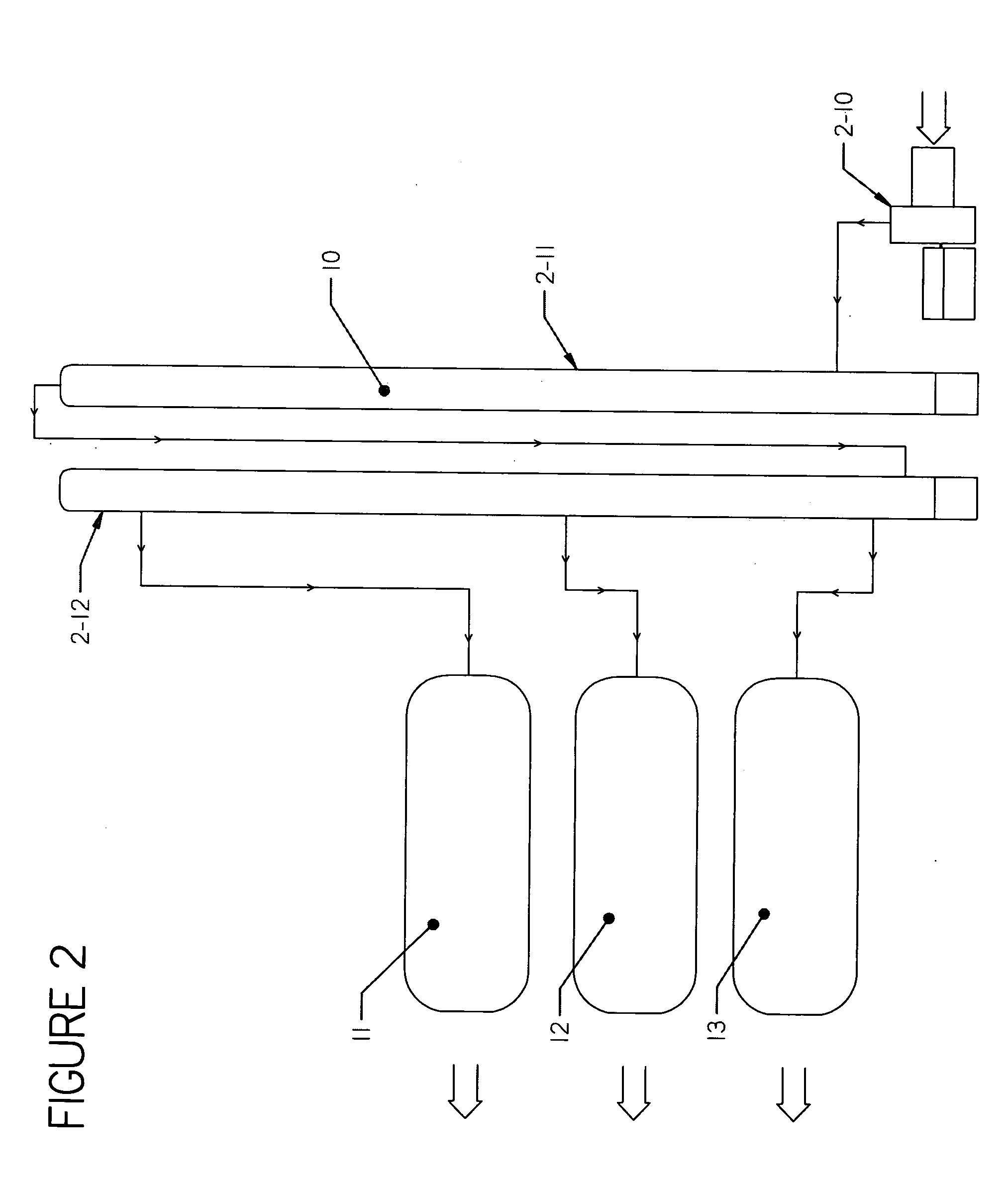
Air Separator Unit 10 (FIG. 2)

The air separator unit 10 separates air into its components parts; oxygen, nitrogen and argon. Trace gases normally present in air are vented. Gaseous air is compressed by a turbine compressor 2-10 and passes into condensing column 2-11 where the compressed gases are cooled and condensed into liquids. The liquids then pass into a fractionating tower 2-12 where they are heated and separated by their boiling points. The separated, purifi...


PUM


Abstract

An oxygen-based biomass solid fuel combustion system and method has an air separator for separating oxygen from air providing a supply of oxygen for feeding oxygen to a solid fuel combustion chamber. An airlock feeds a metered amount of solid fuel to the solid fuel combustion chamber. A burner stage having a firetube for collecting fuel gases from the solid fuel combustion chamber combusts the collected fuel gases with further oxygen from the separator and heats a boiler to generate steam. A heat utilization device (e.g. an electrical generator) may be connected to the steam boiler. Nitrogen-free diluent gases (e.g. argon and carbon dioxide) are used to control combustion process temperatures. The usable heat energy and useful byproducts are extracted from the different stages of the process.

Description

BACKGROUND AND BRIEF DESCRIPTION OF THE INVENTION The present invention relates to a gasifier system and method for the efficient conversion of solid fuel waste materials (tires, etc.) and biomass materials into usable energy and useful products. DESCRIPTION OF THE PRIOR ART The prior art is best exemplified by U.S. Pat. No. 5,284,103 entitled BIO-MASS BURNER CONSTRUCTION by Hand et al, which is a division of U.S. Pat. No. 5,178,076 entitled BIO-MASS BURNER CONSTRUCTION issued Jan. 12, 1993 to the same inventors. In these patents, the burner utilizes a first burning chamber having a falling fuel entrained bed zone positioned above a traveling grate having a porous metallic woven belt. Primary air is directed through the porous belt to establish an oxygen-starved first burning chamber. A second burning chamber in fluid communication with the first burning chamber has a restricted diameter and effectively provides a hot-air gas nozzle. In larger sized units, a plurality of conveyors...

Claims


Application Information

Patent Timeline
IPC IPC(8): C10J1/00F23G5/00F23G5/027F23G5/16F23G5/46F23G7/10F23J15/02F23J15/04F23L7/00
CPCF23G5/006Y02E20/344F23G5/16F23G5/46F23G7/10F23G2201/40F23G2203/8016F23G2205/18F23G2206/203F23J15/02F23J15/04F23J2217/101F23J2217/40F23L7/007F23L2900/07001Y02E20/12Y02E20/322F23G5/0276Y02E20/32Y02E20/34
Inventor ABRAMS, STAN E.CULVEY, BRIAN
Owner MUNIZ CESAR A
Why Eureka
Try Eureka