
System and method of optical data communication with multiple simultaneous emitters and receivers

a technology of optical data communication and multiple simultaneous emitters, applied in the field of optical networking, can solve problems such as errors in received data, and achieve the effect of reliable wireless communication

Active Publication Date: 2006-03-07
DISNEY ENTERPRISES INC
View PDF40 Cites 25 Cited by
  • Summary
  • Abstract
  • Description
  • Claims
  • Application Information

AI Technical Summary

Benefits of technology

[0014]It is therefore an object of the present invention to provide a means of reliable wireless communication of digital data between simultaneous moving and nonmoving objects.
[0015]The system and method of the present invention involves optically transmitting redundant packets of data using infrared signals at pseudo-random intervals to allow a receiver to distinguish between multiple simultaneous sources. The emitters repeatedly transmit a short packet at randomized intervals much shorter than the frame rate. The frame rate is defined as the amount of time by which data must be successfully transmitted from an emitter to a receiver. The frame rate is determined by the application. Statistical analysis shows that the probability of collision of the desired packet with a packet from some other source is sufficiently low such that timely reception of at least one uncorrupted packet in the required time frame (frame rate) is assured. Packet collision causes errors in the received data, detectable by the receiver when compared with a checksum included with the data. The high redundancy of emitted data also aids in reception in poor environmental conditions.
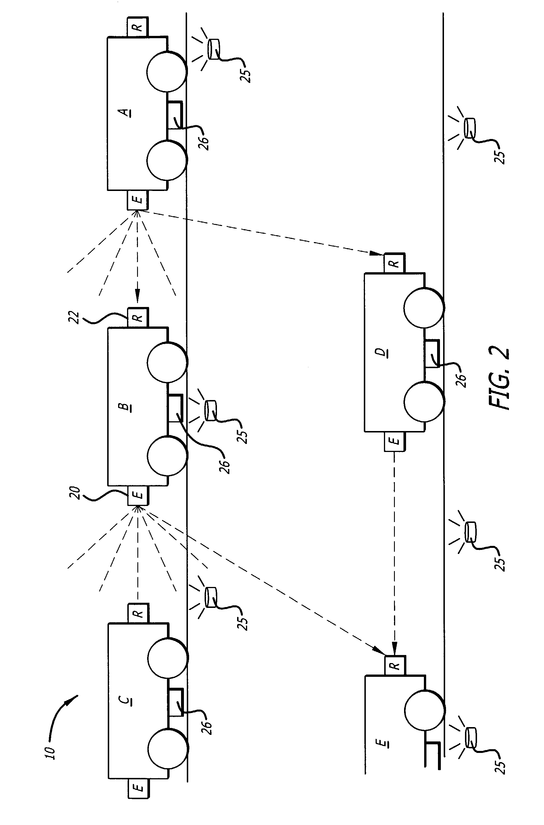
[0018]Operating characteristics of the system of the present invention are furthermore a function of the optical power of the emitters, sensitivity of the receivers / optics which determine the distance at which receivers will reliably obtain data from transmitters. The system will not pass through bad data due to marginal reception conditions.

Problems solved by technology

Packet collision causes errors in the received data, detectable by the receiver when compared with a checksum included with the data.
If they are found to be corrupted, they are thrown away.

Method used


Image

  • System and method of optical data communication with multiple simultaneous emitters and receivers
  • System and method of optical data communication with multiple simultaneous emitters and receivers
  • System and method of optical data communication with multiple simultaneous emitters and receivers

Examples


Embodiment Construction

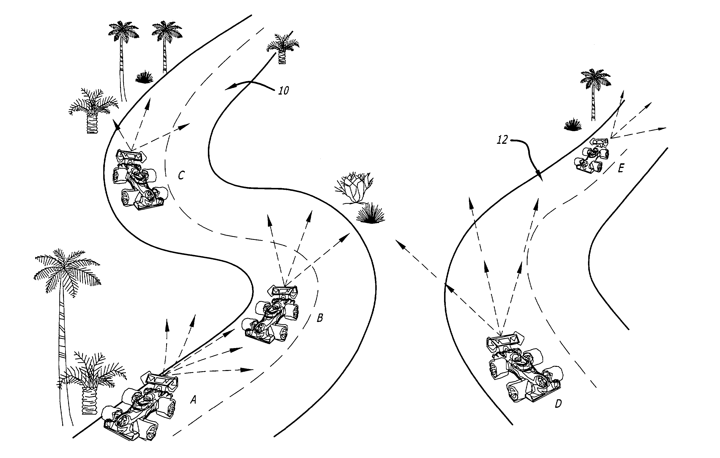
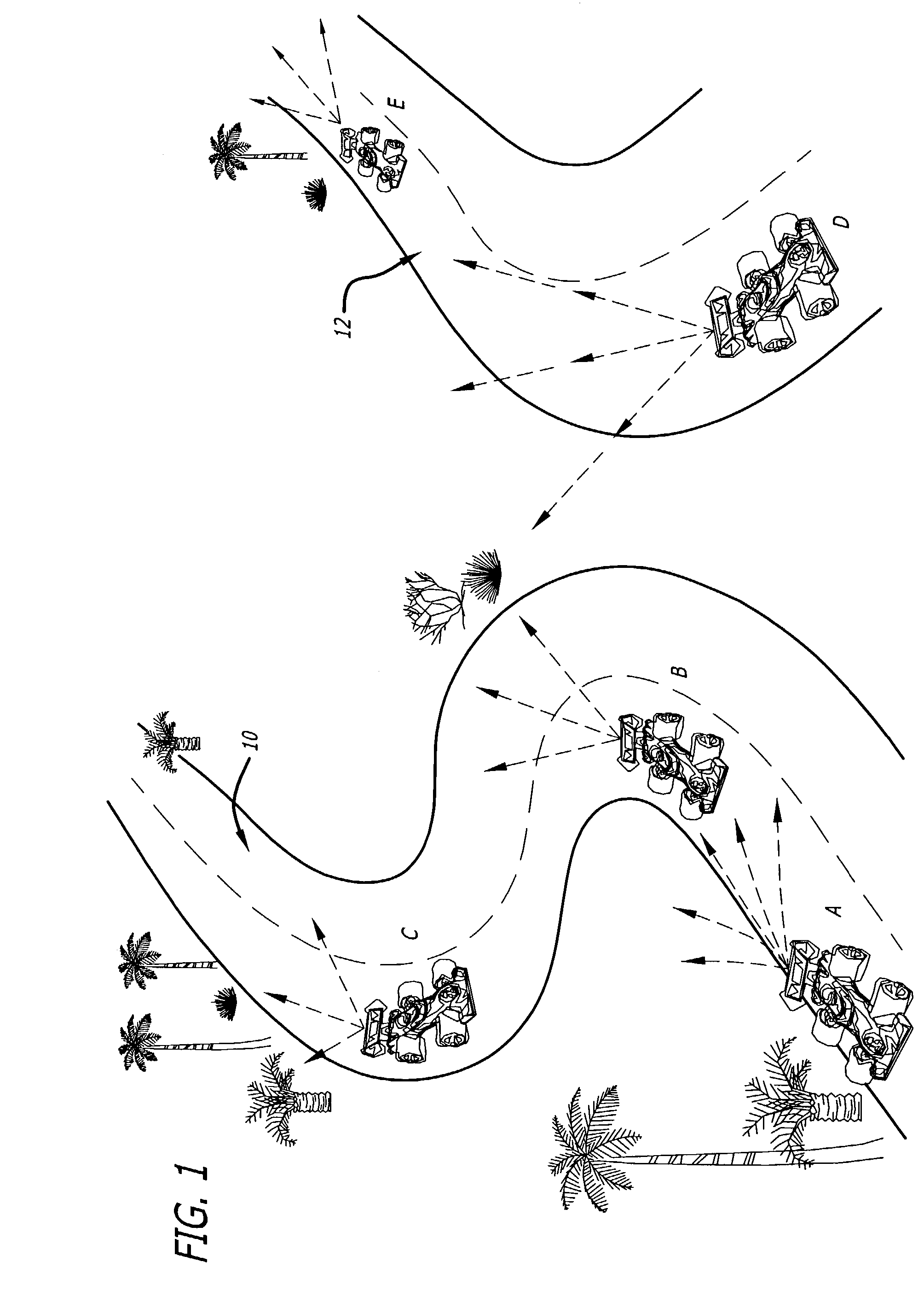
[0027]As mentioned above, one application for the optical data communication method of the present invention is to provide communications directly between vehicles for purposes of maintaining distance and required closing speed. In an exemplary embodiment of the present invention, a speedway ride system utilizes the optical data communication method of the present invention to communicate speed from each leading vehicle to the vehicle behind it so that the vehicles do not collide with each other.

[0028]The speedway racing system comprises a plurality of vehicles operated by guests traveling simultaneously on a plurality of tracks. It is desired to prevent guests from colliding with other vehicles, since collisions can cause injuries. Collisions can be avoided by ensuring that the speed of a vehicle is not sufficiently fast to catch up to the vehicle ahead of it and hit it. Such collisions can be detected and prevented if each vehicle knows the speed of the vehicle ahead of it, as wel...


PUM


Abstract

The system and method of the present invention optically transmits redundant packets of data using infrared signals at pseudo-random intervals to allow a receiver to distinguish between multiple simultaneous sources. The emitters repeatedly transmit a short packet at randomized intervals much shorter than the frame rate. Statistical analysis shows that the probability of collision of the desired packet with a packet from some other source is sufficiently low such that timely reception of at least one uncorrupted packet in the required time frame is assured.

Description

BACKGROUND OF THE INVENTION[0001]1. Field of the Invention[0002]The invention relates to optical networking. More particularly, the invention relates to a system and method of optical networking among multiple simultaneous transmitters and receivers.[0003]2. General Background and State of the Art[0004]There are many applications where digitally-encoded information must be transmitted in a timely and reliable fashion between stationary to stationary, stationary to mobile, or mobile to mobile systems. Optical carriers, usually of infrared wavelength, or radio frequency signals are often used for communication in such applications where wired connections are impractical. Due to the inherently different properties of both optical and radio frequency signals, the use of one type of signal may be appropriate in applications where others are not.[0005]For example, optical signals require that objects in communication have a clear line of sight between each other. Radio frequency signals, ...

Claims


Application Information

Patent Timeline
IPC IPC(8): B60Q1/00H04B10/00H04B10/10H04J
CPCH04B10/1149
Inventor OLCH, RONALD HOWARD
Owner DISNEY ENTERPRISES INC
Learn More