Array antenna apparatus utilizing a nonlinear distortion compensator circuit

a compensation circuit and array antenna technology, applied in the direction of polarisation/directional diversity, transmission monitoring, instruments, etc., can solve the problems of deteriorating beam control accuracy, consumption power, and nonlinear distortion caused by amplification, so as to reduce the size of the apparatus, suppress the effect of beam control accuracy from deterioration and improve power efficiency

Active Publication Date: 2006-03-07
PANASONIC CORP
View PDF5 Cites 9 Cited by
  • Summary
  • Abstract
  • Description
  • Claims
  • Application Information

AI Technical Summary

Benefits of technology

[0025]With this configuration, because a required amount of distortion compensation is made on each antenna array, beam control accuracy is suppressed from deteriorating without having a bad effect upon the other adjacent antenna arrays. Meanwhile, the distortion adding sections, for both di

Problems solved by technology

However, the nonlinear distortion caused upon amplification by the power amplifier forms a factor to deteriorate beam control accuracy over the array antenna apparatus.
Due to this, the array antenna apparatus is configured high in beam control accuracy, small in size but low in consumption power.
However, the array antenna apparatus having distortion compensator circuits for the power amplifiers on part of antenna arrays has a problem that beam control accuracy deteriorates under the influence of a distortion caused by the power amplifier on the array not having a distortion addin

Method used


Image

  • Array antenna apparatus utilizing a nonlinear distortion compensator circuit
  • Array antenna apparatus utilizing a nonlinear distortion compensator circuit
  • Array antenna apparatus utilizing a nonlinear distortion compensator circuit

Examples


embodiment 1

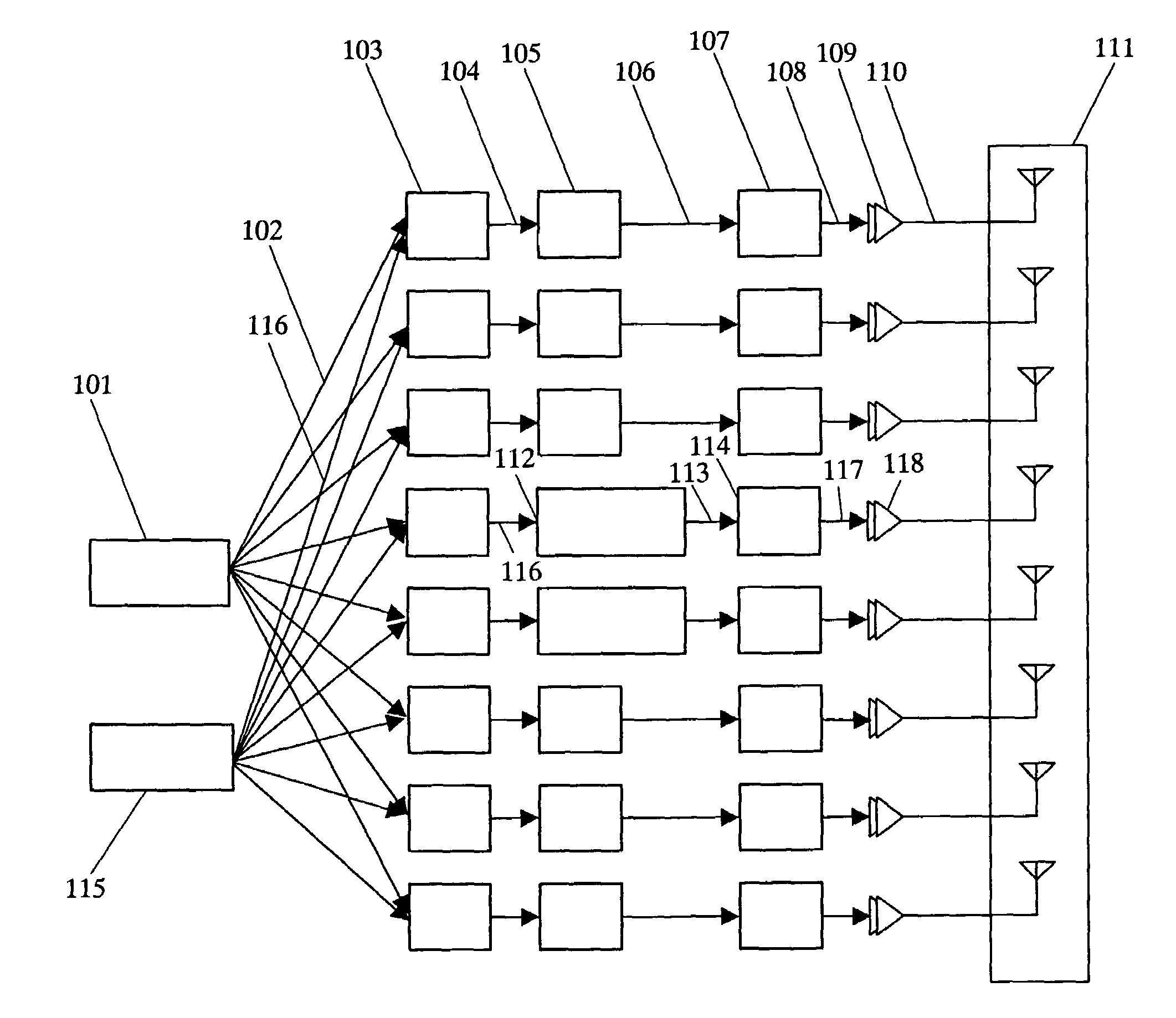
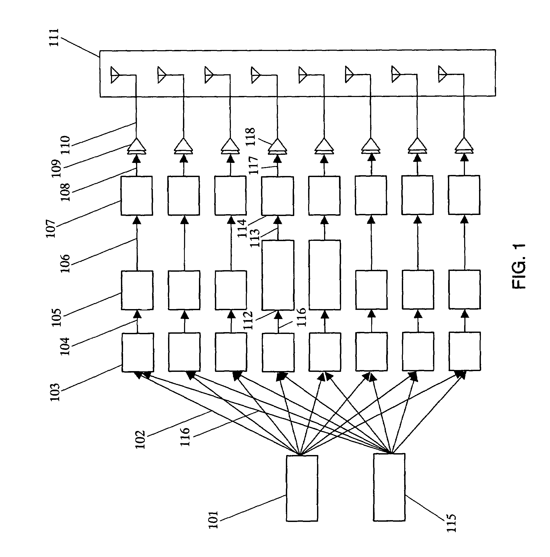
[0049]FIG. 1 shows a configuration of an array antenna apparatus of the present embodiment.

[0050]A signal generating section 101 is to generate a transmission IQ signal 102. A beam-direction control section 115 is to compute amplitude weights and phase rotation amounts suited for respective antenna arrays such that the total radiation patterns by a linear array antenna 111 are formed to a predetermined form, and outputs a beam-direction control signal 116 to amplitude-phase control sections103. The amplitude-phase control section 103 is to control an amplitude and phase of a transmission IQ signal 102 in order to control the beam to a direction as designated by a beam-direction control signal 116, thereby outputting a transmission IQ signal 104. Specifically, the amplitude-phase control sections 103 of the linear array antenna are controlled with a gradually smaller amplitude as positioned closer to the end from the center. However, a phase is o degree at a centered antenna array. A...

embodiment 2

[0115]FIG. 7 shows a configuration of an array antenna apparatus according to the present embodiment.

[0116]This is different from the configuration of embodiment 1 shown in FIG. 1, in that an instantaneous power computing section 713 is added and in that amplification-phase distortion adding sections 112 and amplification distortion adding sections 105 are not connected.

[0117]In FIG. 7, an instantaneous power level computing section 713 is to compute a power level of input signal and output an instantaneous power level signal 714 commensurate therewith.

[0118]Also, an amplitude-phase control section 703 is different from the amplitude-phase control section 103 of embodiment 1 in that amplitude weighting and phase rotation are carried out depending upon not only a beam-direction control signal but also an instantaneous power level signal. FIG. 8 shows a configuration of the amplitude-phase control section of this embodiment.

[0119]In FIG. 8, the I signal 1101 and the Q signal 1102, inp...

embodiment 3

[0135]FIG. 9 shows a configuration of a circular array antenna apparatus according to the present embodiment. This is different from the configuration of embodiment 1 shown in FIG. 1 in that a rewrite control section 816 is added, an amplitude-phase control section 103, amplitude-phase distortion adding section 112 and amplitude distortion adding section 805 are configured by a reconfigurable device (rewritable circuit) that is a device capable of circuit-rewriting, and the array antenna is of a circular array antenna.

[0136]In FIG. 9, the amplitude-phase control sections 103, the amplitude distortion adding sections 105 and the amplitude-phase distortion adding sections 112 are included in a digital processing section 815. This digital processing section 815 is a circuit rewritable device, one example of which is in practical application as SDR (Software defined radio). The digital processing section 815 makes a rewriting, based on each antenna array, into a combination of amplitude...


PUM


Abstract

Amplitude phase distortion adding sections are provided for the power amplifiers on the antenna arrays greater in amplitude weighting while amplitude distortion adding sections are provided for the power amplifiers on the antenna arrays smaller in amplitude weighting. Due to this, because a required amount of distortion compensation is made based on each antenna array, there is no bad effect upon the adjacent other antenna array, suppressing the deterioration in beam control accuracy. This, also, reduces the size of the apparatus and improves the power efficiency on the array antenna apparatus overall.

Description

FIELD OF THE INVENTION[0001]This invention relates to an array antenna apparatus, for use on a communications apparatus of a radio communications system, having a nonlinear distortion compensator to compensate for a nonlinear distortion caused over a transmission system.BACKGROUND OF THE INVENTION[0002]There is known an antenna array apparatus arranging a plurality of antennas to thereby control the directivity thereof, as an antenna apparatus included in a transmitter of a radio communications system.[0003]By using such an array antenna apparatus, a beam having an acute directivity can be formed in a desired direction. This enables control, to raise the frequency utilization efficiency by reducing the repeated distance at the same frequency, or to control the null point in order not to radiate a radio wave in unwanted directions.[0004]The array antenna, generally, has a plurality of antennas. The antennas are respectively connected with power amplifiers for supplying signals. RF si...

Claims


Application Information

Patent Timeline
IPC IPC(8): H04B1/04H01Q3/26G01S7/40H01Q21/06H03F1/32H04B7/08H04B7/10
CPCH01Q19/30
Inventor UKENA, MASATOTAKABAYASHI, SHINICHIROORIHASHI, MASAYUKI
Owner PANASONIC CORP
Why Eureka
Try Eureka