

Thermal transfer film and image forming method
a technology of thermal transfer film and image forming method, which is applied in the field of thermal transfer film, can solve the problems of reducing flowability, affecting the appearance of printed materials, and affecting the flowability of intermediate layers, and achieve the effect of preventing secret leakag
- Summary
- Abstract
- Description
- Claims
- Application Information
AI Technical Summary
Benefits of technology
Problems solved by technology
Method used
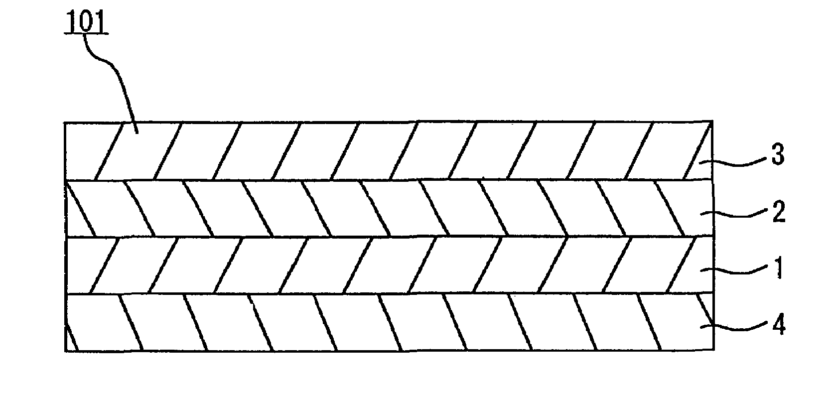
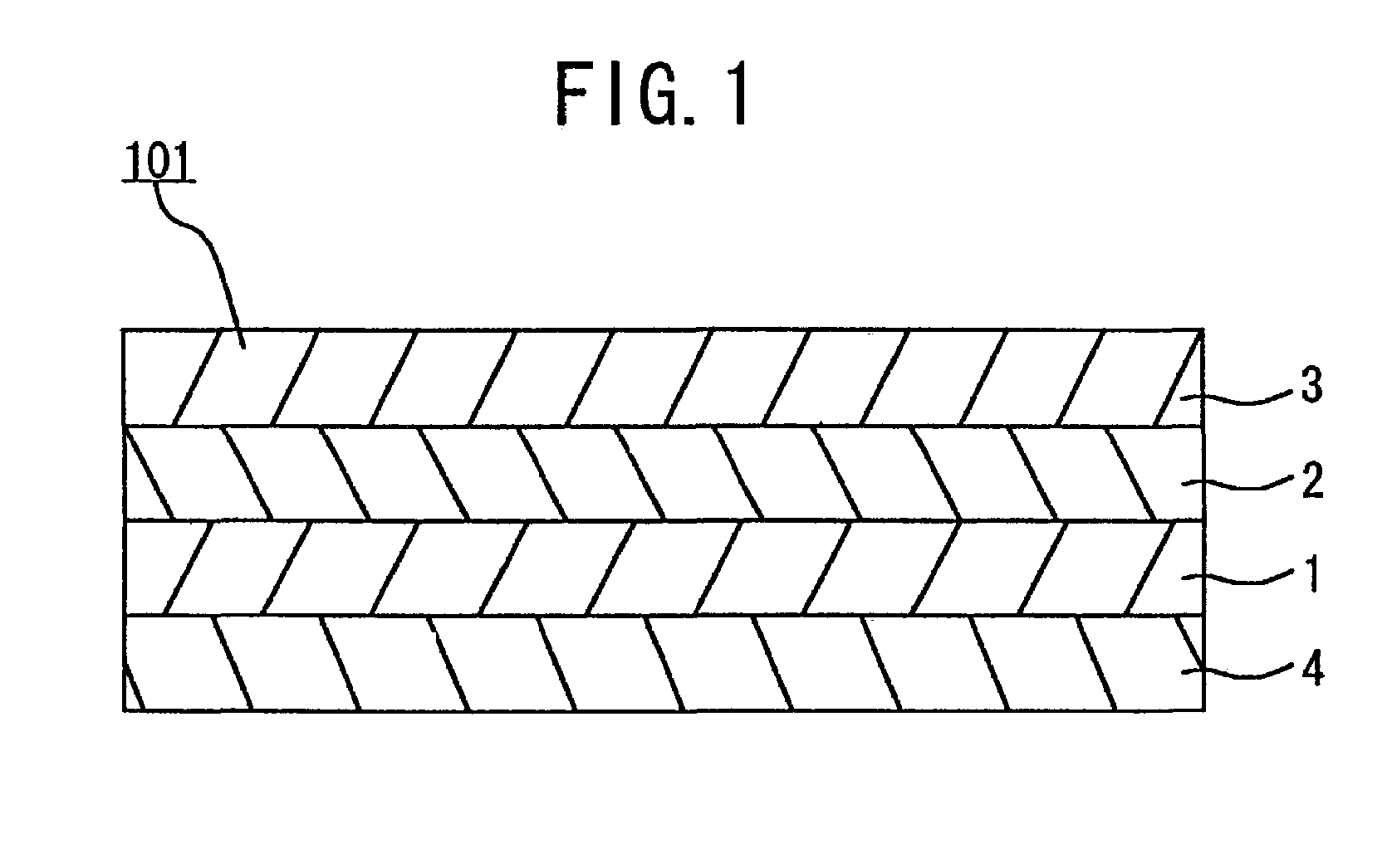
Image

Examples
example 1
Preparation of Samples 1 to 12
[0108]A polyethylene terephthalate film with a thickness of 4.5 μm (manufactured by Toray Corporation) was used as a substrate film, and an intermediate layer coating solution with each composition shown in Table 1 below was coated by gravure coating at each coating weight shown in Table 1 below on the substrate film, which was dried by a hot wind at 100° C. and then wound. The melt viscosity was measured with the device described below under the measurement conditions described below.
[0109]Name of device: Viscoelasticity measurement device Rotovisco RV20 (manufactured by HAKKE)
[0110]Measurement head: M5
[0111]Sensor system: Sensor system cone plate PK5
[0112](aperture angle 0.5°, radius of cone plate 25 mm)
[0113](Temperature setting: two temperatures which are 15° C. and 25° C. higher than the fuse peak temperature of the thermally fusible substance)
[0114]Subsequently, a coloring layer coating solution with the following composition heated at 100° C. was...
example 2
Preparation of Samples 2-1 to 2-5
[0179]A polyethylene terephthalate film with a thickness of 4.5 μm (manufactured by Toray Corporation) was used as a substrate film, and an intermediate layer coating solution with the following composition was coated by gravure coating at a coating weight of 0.5 g / m2 on the substrate film, which was dried by a hot wind at 100° C. and then wound.
[0180]
Thermally fusible substance 20 parts(Placcel 220, manufactured by Daicel ChemicalIndustries, Ltd.)(fuse peak temperature: 55° C., crystallization peaktemperature: 28° C.)(melt viscosity at 70° C.: 590 mPa · s)(melt viscosity at 80° C.: 430 mPa · s)(number average molecular weight: 2,000)Binder resin (polyester resin) 60 parts(Vylon 200, manufactured by Toyobo Co., Ltd.)(softening temperature: 163° C., intermediate glasstransition temperature: 67° C.)(number average molecular weight: 15,000 to 20,000)Carbon black 20 parts(average particle diameter 40 nm, manufactured byMitsubishi Chemical Co., Ltd.)Tolue...
examples 3-1 to 3-5
Preparation of Samples 3-1 to 3-5
[0214]A polyethylene terephthalate film with a thickness of 4.5 μm (manufactured by Toray Corporation) was used as a substrate film, and an intermediate layer coating solution with the following composition was coated by gravure coating at a coating weight of 0.5 g / m2 on the substrate film, which was dried by a hot wind at 100° C. and then wound.
[0215]
Thermally fusible substance20 parts(Placcel 220, manufactured by Daicel Chemical Industries,Ltd.)(fuse peak temperature: 55° C., crystallization peaktemperature: 28° C.)(melt viscosity at 70° C.: 590 mPa · s)(melt viscosity at 80° C.: 430 mPa · s)(number average molecular weight: 2,000)Binder resin (polyester resin)60 parts(Vylon 200, manufactured by Toyobo Co., Ltd.)(softening temperature: 163° C., intermediate glasstransition temperature: 67° C.)(number average molecular weight: 15,000 to 20,000)Carbon black20 parts(average particle diameter 40 nm, manufactured byMitsubishi Chemical Co., Ltd.)Toluene9...
PUM
| Property | Measurement | Unit |
|---|---|---|
| softening temperature | aaaaa | aaaaa |
| softening temperature | aaaaa | aaaaa |
| softening temperature | aaaaa | aaaaa |
Abstract
Description
Claims
Application Information