Organic light emitting materials and devices

a light-emitting material and organic technology, applied in the direction of discharge tube luminescnet screens, other domestic articles, natural mineral layered products, etc., can solve the problems of energy loss, energy loss, energy loss, etc., and achieve the effect of improving stability and improving electrophosphorescen

Inactive Publication Date: 2006-03-14
UNIVERSAL DISPLAY +1
View PDF25 Cites 31 Cited by
  • Summary
  • Abstract
  • Description
  • Claims
  • Application Information

AI Technical Summary

Benefits of technology

[0019]Specific embodiments of the present invention are directed to OLEDs using emissive phosphorescent organometallic compounds that produce improved electrophosphorescence in the blue region of the visible spectrum. The emissive material itself is also provided. The emissive material may have improved stability, and may provide a saturated blue emission.

Problems solved by technology

The remaining excitons in a fluorescent device, which are produced in the lowest triplet excited state of an organic molecule, are typically not capable of being converted into the energetically unfavorable higher singlet excited states from which the fluorescence is produced.
This energy, thus, becomes lost to radiationless decay processes that heat-up the device.

Method used

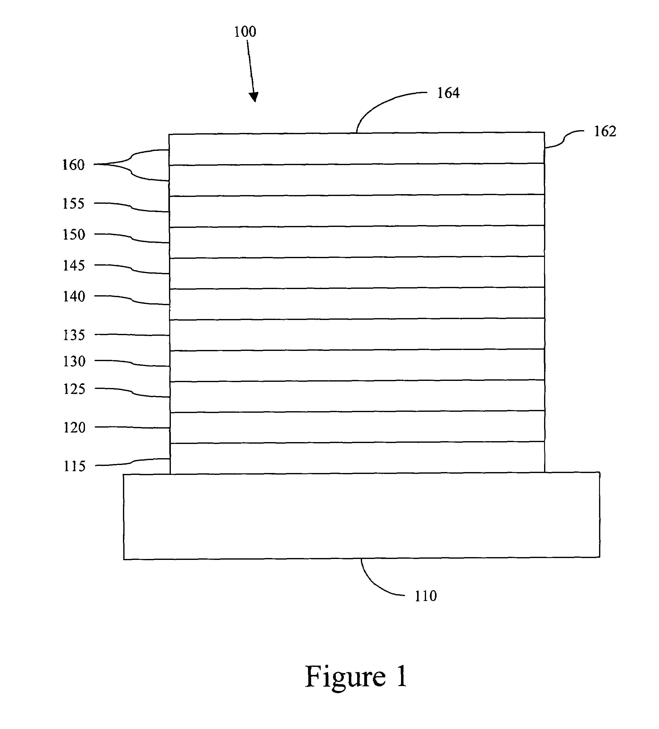
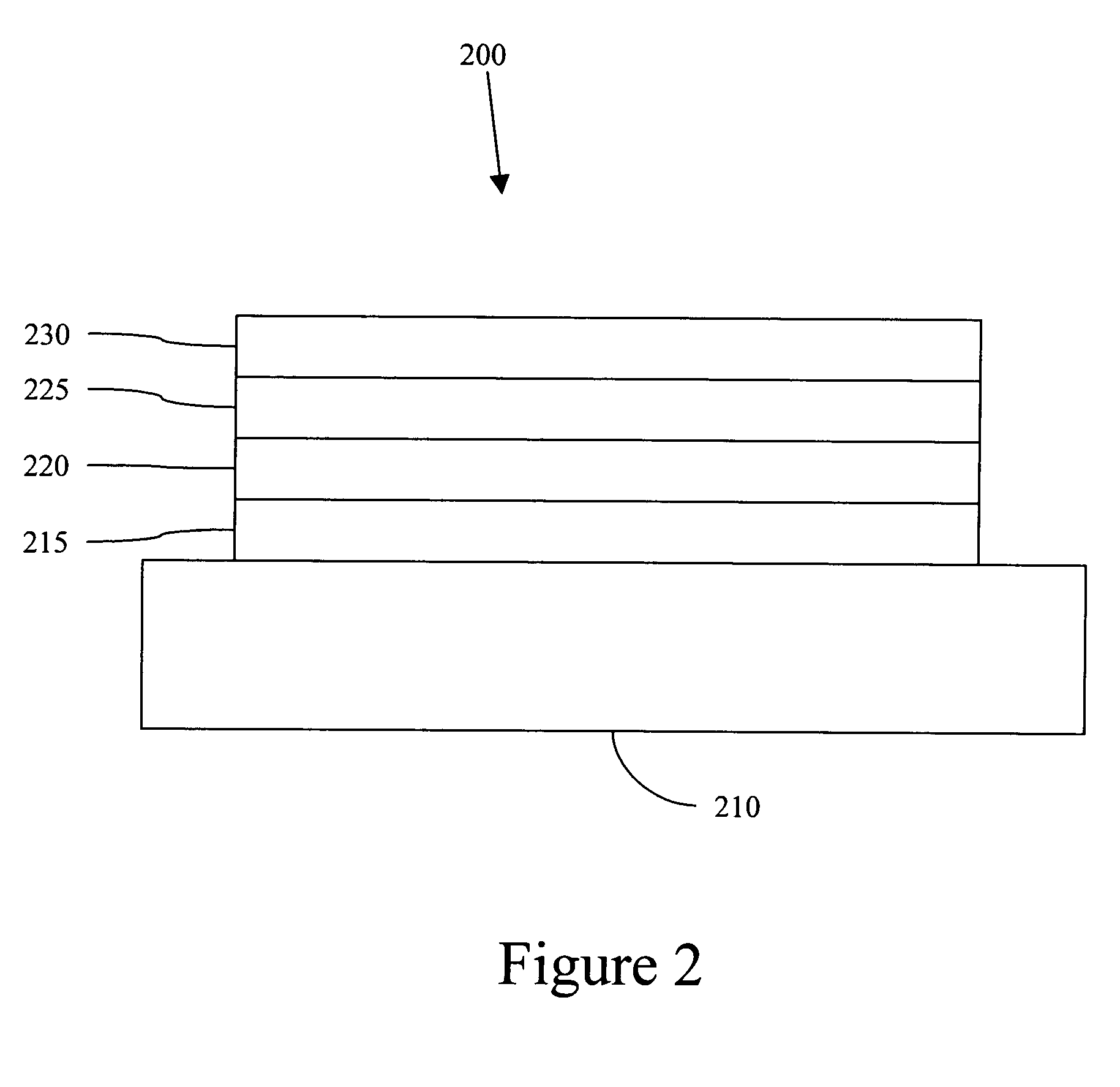
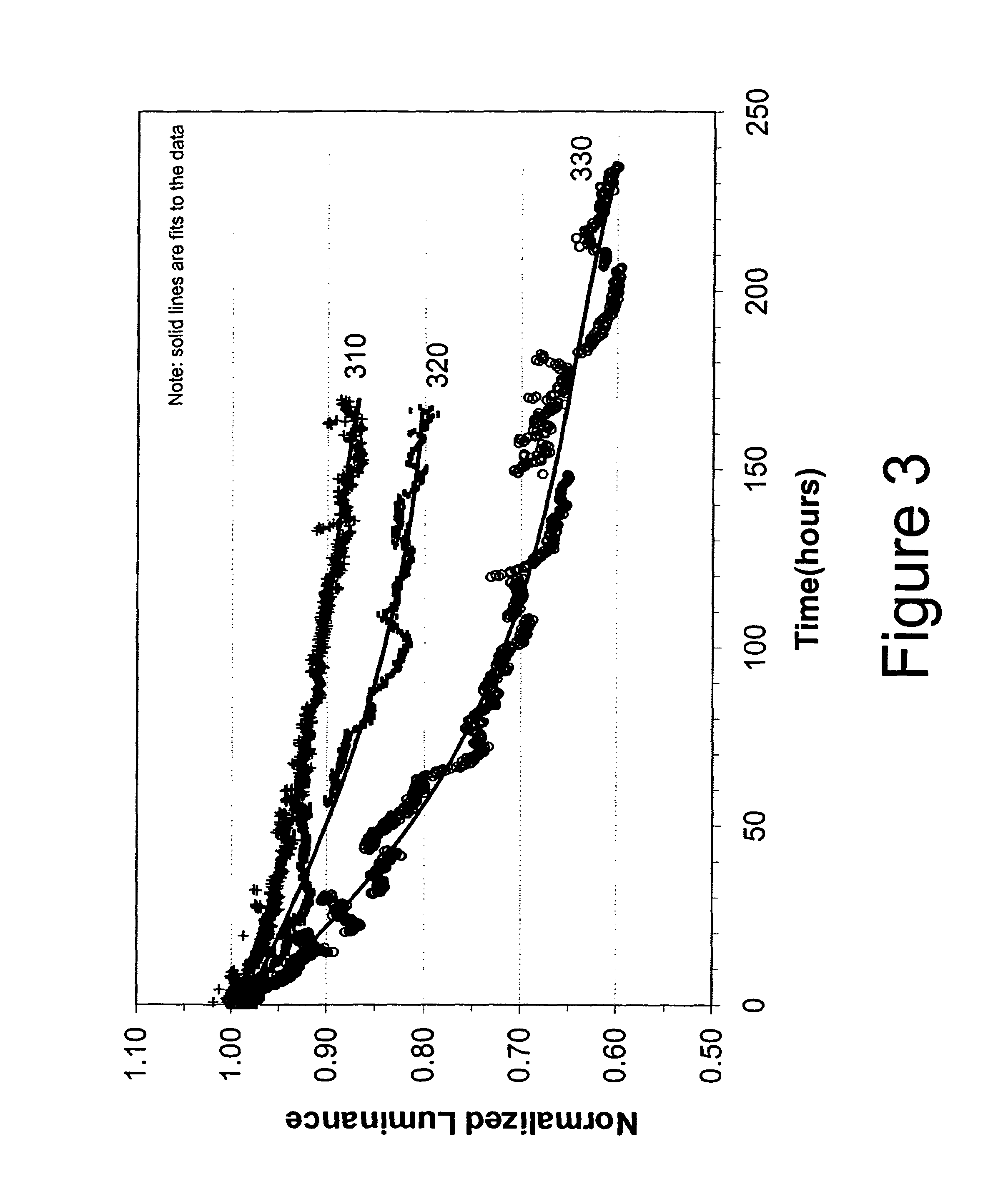

Image

  • Organic light emitting materials and devices
  • Organic light emitting materials and devices
  • Organic light emitting materials and devices

Examples


example 1

[0120]STEP 1: 3,5-Bis(trifluoromethyl)phenylboronic acid (13.5 g, 52 mmol), 2-bromopyridine (6.2 g, 39 mmol), palladium (II) acetate (0.29 g, 1.3 mmol), triphenylphosphine (1.36 g, 5.2 mmol), and sodium carbonate (7 g, 68 mmol) were added to 200 mL. of 1,2-dimethoxyethane and 100 mL. of water. The reaction mixture was heated to reflux for 5 hours and after cooling, 100 mL of water and 100 mL. of ethyl acetate were added. The phases were separated, the organic layer was dried over magnesium sulfate and the excess solvent was removed. 2-(3,5-Bistrifluoromethylphenyl)pyridine was purified by column chromatography and collected as a white solid (7.1 g).

[0121]STEP 2: 2-(3,5-Bis(trifluoromethyl)phenyl)pyridine (1.4 g, 4.8 mmol) from Step 1 above and iridium (III) chloride hydrate (0.87 g, 2.4 mmol) were added to a flask containing 15 mL. of 2-methoxyethanol and 5 mL. of water. The reaction was heated to reflux for 16 hours and allowed to cool. The yellow precipitate that formed was collec...

example 3

[0123]STEP 1: 2,4-Difluoro-5-(trifluoromethyl)bromobenzene (2.0 g, 7.7 mmol), 2-tributylstannylpyridine, and Bis(triphenylphosphine)palladium(II)chloride (0.16 g, 0.23 mmol) were added to 50 mL. xylenes and the mixture was heated to reflux for 16 hours. The reaction mixture was filtered through a silica gel plug and then purified with column chromatography to give 2-(2,4-difluoro-5-trifluoromethylphenyl)pyridine (1.4 g, 5.4 mmol). The product was confirmed by Mass Spectroscopy and 1H NMR.

[0124]STEP 2: 2-(2,4-difuoro-5-trifuoromethylpenyl)pyridine (1.4 g, 5.4 mmol) and iridium (III) chloride hydrate (0.97 g, 2.7 mmol) were added to 10 mL. of 2-methoxyethanol and 3 mL. water. The reaction was heated for 16 hours and a light green precipitate was collected by vacuum filtration and washed with ethanol and hexanes. The dichloro-bridged dimer was dried in a vacuum oven to give 1.0 g (50% yield). The product was used directly in the next step without further purification.

[0125]STEP 3: The ...


PUM

PropertyMeasurementUnit
wavelengthaaaaaaaaaa

Abstract

An organic light emitting device is provided. The device has an anode, a cathode, and an emissive layer disposed between the anode and the cathode, the emissive layer further comprising an emissive material having the structure:
wherein each of the variables are defined herein.

Description

RESEARCH AGREEMENTS[0001]The claimed invention was made by, on behalf of, and / or in connection with one or more of the following parties to a joint university-corporation research agreement: Princeton University, The University of Southern California, and Universal Display Corporation. The agreement was in effect on and before the date the claimed invention was made, and the claimed invention was made as a result of activities undertaken within the scope of the agreement.REFERENCE TO RELATED APPLICATIONS[0002]This application is related to and claims priority from U.S. Provisional Patent Application 60 / 404,213 filed Aug. 16, 2002 and is a continuation-in-part of U.S. patent application Ser. No. 10,288,785 filed Nov. 6, 2002, Now U.S. Pat. No. 6,916,554, also entitled “Organic Light Emitting Materials and Devices”, each of which is incorporated herein in its entirety.FIELD OF THE INVENTION[0003]The present invention is directed to phosphorescence based organic light emitting material...

Claims


Application Information

Patent Timeline
Patent Type & Authority Patents(United States)
IPC IPC(8): C09K11/06H05B33/14C07F15/00H01L51/30H01L51/50
CPCC07F15/004C09K11/06H01L51/0085C09K2211/1007C09K2211/1011Y10S428/917C09K2211/185H01L51/5016C09K2211/1029H10K85/342H10K50/11H10K2101/10H05B33/14
Inventor THOMPSON, MARK E.DJUROVICH, PETERKWONG, RAYMONDTUNG, YEH-JIUNKNOWLES, DAVID B.BROOKS, JASONWALTERS, ROBERT W.MA, BIN
Owner UNIVERSAL DISPLAY
Why Eureka
Try Eureka