Method and apparatus for making welded large pipes

a technology for welded pipes and pipes, applied in the field of methods and apparatus for making welded large pipes, can solve the problems of time-consuming and costly pipe transportation, and inability to meet the needs of customers, and achieve the effect of preventing edge offset, preventing roof formation, and good, destruction-free and inspection-free surface contour of welded seams

Inactive Publication Date: 2006-03-14
MANNESMANN ROHRENWERKE
View PDF11 Cites 13 Cited by
  • Summary
  • Abstract
  • Description
  • Claims
  • Application Information

AI Technical Summary

Benefits of technology

[0020]The present invention resolves prior art problems by manufacturing the large pipe or helical-seam pipe through laser welding, and by integrating the process control at the end of the actual production process to make a machine-ready high-quality pipe. As a consequence, the manufacturing chain is significantly shortened and a greatly simplified assembly can be designed that enables concentration of essential components of the manufacturing process, including continuous process control, to the actual welding device. Suitably, the plant design is realized as modular system in the form of main structural groups that can, easily be assembled and disassembled so as to afford great mobility to move from site to site. In addition, the process according to the present invention is able to produce machine-ready helical-seam pipes of high quality, as a consequence of the following features:
[0062]Production of a welded large pipe with better cylindrical inner and outer contours, whereby the inner and outer surfaces of the pipe are not interrupted or interfered with by a circumferential weld camber, as is the case in submerged-arc welding.

Problems solved by technology

Oftentimes, these regions are characterized by a shortness of water and underdeveloped infrastructure.
As a result, transport of pipes and logistics becomes time-consuming and costly.
In addition, the economy of countries in such regions is frequently precarious and foreign currencies are scarce so that attempts are underway to avoid import of goods and to increase own efforts to satisfy the demand.
This process is thus time-consuming and unsuitable to satisfy demands for current welding techniques and continuous process control.
As this process is intended for a long-term stationary operation, its application is also unsuitable for single-purpose plants which require a quick set up and which can be quickly put into operation.
In summary, the process described in the Stahlrohr Handbuch has the following shortcomings:very long manufacturing chain with many inspection and control steps, resulting in a very outsized and cost-intensive structure;transfer of the plant from site to site (mobility) is cost-intensive and time-consuming;submerged-arc welding results in a relatively large-volume melt bath that makes the use of modern systems for quality assurance difficult;submerged-arc welding normally requires Y joint or double-Y-joint as edge preparation, accompanied by an increase in welding additives (welding wire and powder) in dependence of the sheet thickness and resulting in larger melt baths, higher risk for flaws, and welding costs;the size of the melt bath adversely affects, depending on the pipe diameter (curvature of the pipe wall), an increase of the welding speed.
This is especially true when thin-walled pipes are involved;submerged-arc welding results in a significant weld camber at the inner seam and outer seam, thereby adversely affecting a later coating of the inside and outside of the pipe.
The weld camber, on one hand, results also in increased wear of the coating material, and, on the other hand, there is a risk of damage to the outer pipe coating in the area of the weld camber during transport and handling.
This method is unsuitable to produce a machine-ready high quality pipe by way of a mobile plant design.

Method used


Image

  • Method and apparatus for making welded large pipes
  • Method and apparatus for making welded large pipes
  • Method and apparatus for making welded large pipes

Examples


Embodiment Construction

[0067]Throughout all the FIGS., same or corresponding elements are generally indicated by same reference numerals. These depicted embodiments are to be understood as illustrative of the invention and not as limiting in any way. It should also be understood that the drawings are not necessarily to scale and that the embodiments are sometimes illustrated by graphic symbols, phantom lines, diagrammatic representations and fragmentary views. In certain instances, details which are not necessary for an understanding of the present invention or which render other details difficult to perceive may have been omitted.

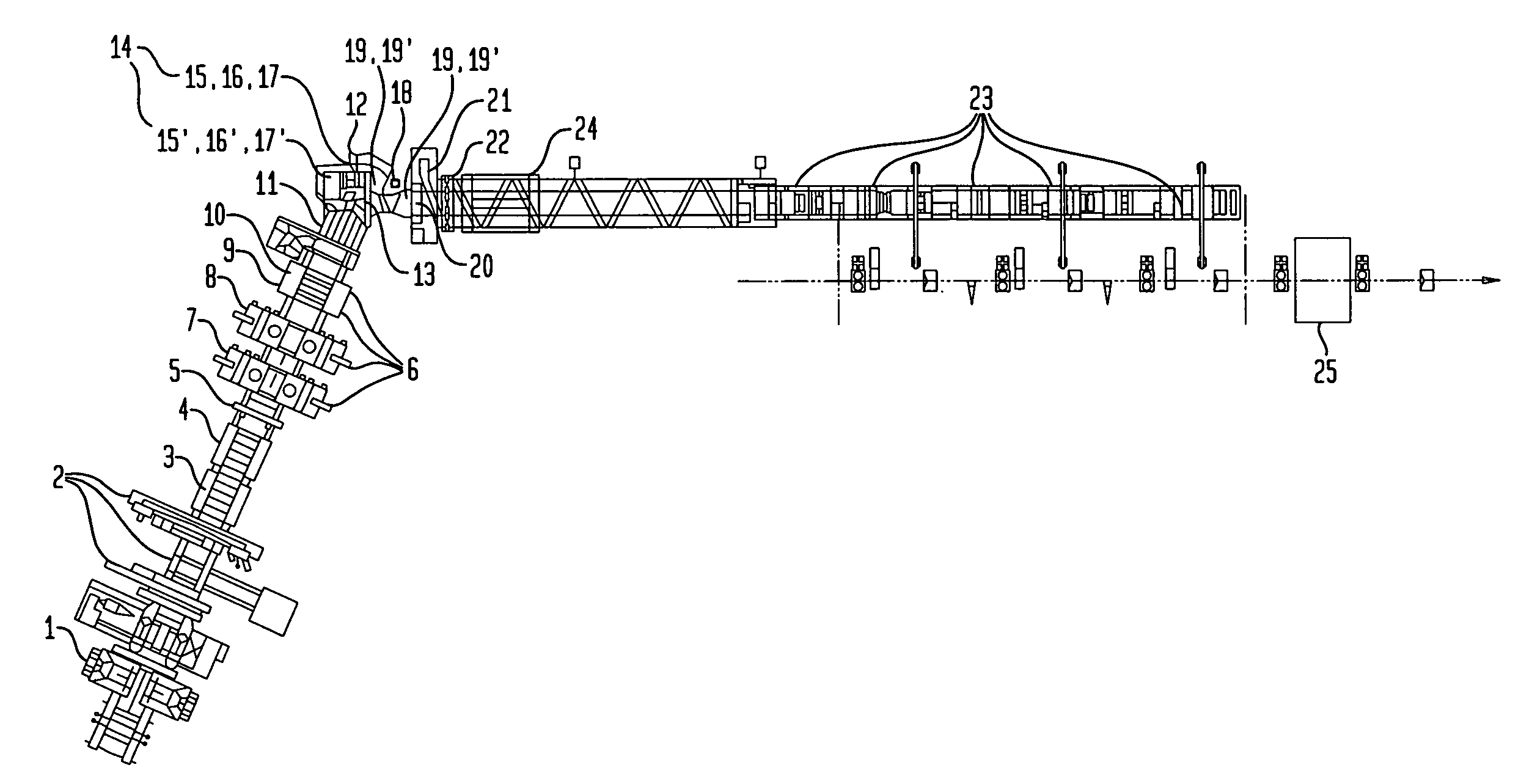
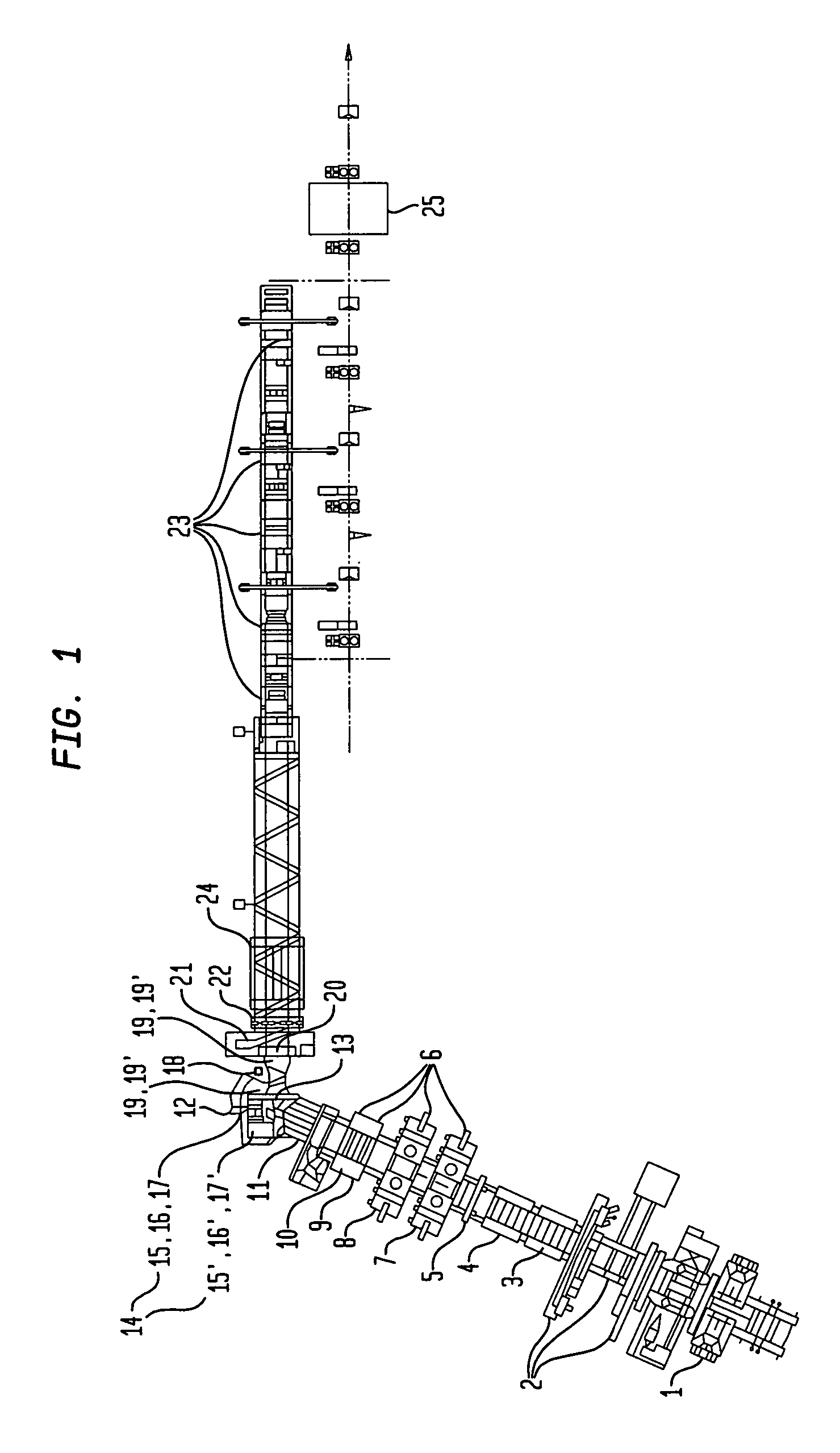
[0068]Turning now to the drawing, and in particular to FIG. 1, there is shown a schematic illustration of a layout of a plant design of an apparatus for making a machine-ready large pipe, in accordance with the present invention. A hot strip wound to a coil upon a coiler 1 pays out from the coiler 1 and has a leading end which is advanced to a welding machine 2 for welding to th...


PUM

PropertyMeasurementUnit
thicknessesaaaaaaaaaa
diameteraaaaaaaaaa
flatnessaaaaaaaaaa

Abstract

In a method and apparatus for making welded large pipes, a leading end of a hot strip is connected to a trailing end of a leader strip and then subjected to a two-stage leveling for strip flatness in transverse direction and strip flatness in longitudinal direction. The entire surface of the hot strip including strip edges thereof is inspected by ultrasound and the strip edges are prepared in four stages before being pre-bent. The hot strip is then shaped into a slotted tube and the strip edges are welded along the inner and outer sides by laser to produce the pipe. Online process diagnostic is provided for monitoring the welding step and the finished welded pipe diameter is measured through online measurement. Online determination of a profile of a welded seam configuration and computer tomographic determination and evaluation of flaws inside the pipe, as well as ultrasonic inspection of the welded seam are further provided.

Description

CROSS-REFERENCES TO RELATED APPLICATIONS[0001]This application claims the priority of German Patent Application, Ser. No. 103 31 000.2, filed Jul. 3, 2003, pursuant to 35 U.S.C. 119(a)–(d), the disclosure of which is incorporated herein by reference.BACKGROUND OF THE INVENTION[0002]The present invention relates to a method and apparatus for making welded large pipes, in particular helical-seam pipes, from hot strip of steel.[0003]Welded large pipes involved here include longitudinally welded pipes or helical-seam pipes, whereby helical-seam pipes are made at a diameter range of about 400 mm to 3050 mm and at wall thicknesses of 5 mm to 30 mm, and involve pipes which are continuously shaped into helical pipes with constant radius of curvature from a hot strip or sheet metal in a shaping device, whereby converging edges of the strip are welded together. Unlike a manufacture of longitudinally welded pipes which require a particular sheet metal width for each pipe diameter, helical-seam...

Claims


Application Information

Patent Timeline
Patent Type & Authority Patents(United States)
IPC IPC(8): B23K26/00B23K10/00B21C37/12B21C51/00B23K26/20B23K26/30B23K31/00B23K101/06B23K103/04
CPCB21C37/122B23K26/305B21C37/126B23K26/302
Inventor TITZE, EBERHARDWERNER, KLAUSKEITEL, STEFFEN
Owner MANNESMANN ROHRENWERKE
Why Eureka
Try Eureka