Modular wireless fixed network for wide-area metering data collection and meter module apparatus

a fixed network and wide-area metering technology, applied in the field of wireless fixed network modules for wide-area metering data collection and meter module apparatus, can solve the problems of large excess capacity, inefficient configuration, and significant limit the number of meters a node can serve, so as to facilitate network planning flexibility, optimize cost and capacity, and increase the effect of infrastructure deployment gradual and cost-efficien

a fixed network and wide-area metering technology, applied in the field of wireless fixed network modules for wide-area metering data collection and meter module apparatus, can solve the problems of large excess capacity, inefficient configuration, and significant limit the number of meters a node can serve, so as to facilitate network planning flexibility, optimize cost and capacity, and increase the effect of infrastructure deployment gradual and cost-efficien

US7012546B1Inactive Publication Date: 2006-03-14SENSUS USA

Image

  • Modular wireless fixed network for wide-area metering data collection and meter module apparatus
  • Modular wireless fixed network for wide-area metering data collection and meter module apparatus
  • Modular wireless fixed network for wide-area metering data collection and meter module apparatus

Examples


first embodiment

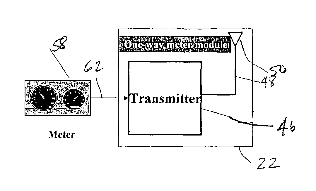
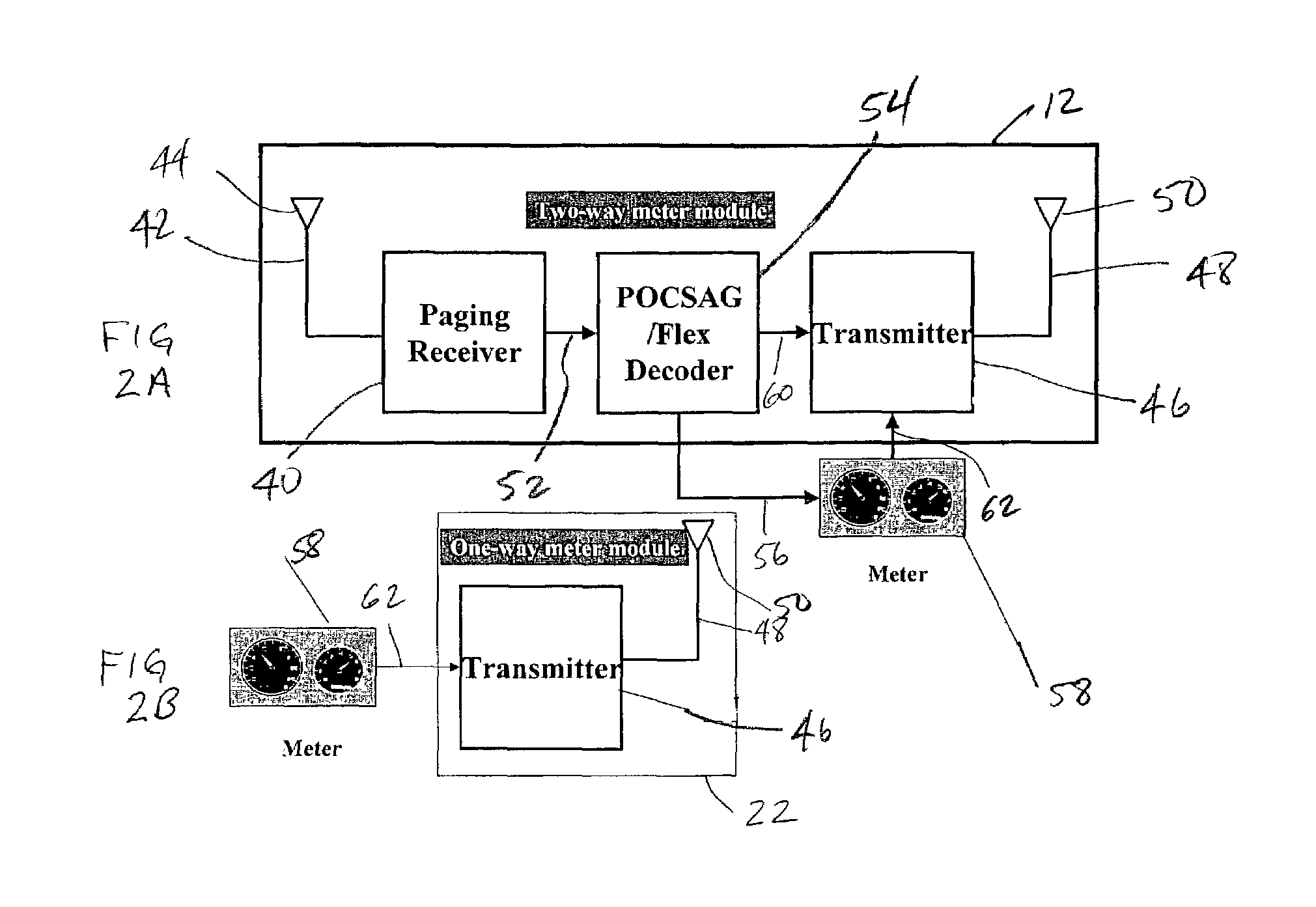
[0089]A one-way meter module 22 (FIG. 2B) transmits a metering data air message once every preprogrammed time interval, and a block diagram of the module is depicted in FIG. 15. In this particular implementation, the module includes a meter interface logic module 180 that collects consumption, tamper status and other data from an associated utility meter 58. It should be noted that although FIG. 15 depicts a single meter interface module 180 for purposes of simplification, multiple meter interface logic modules may be used in a single transmitter to interface with corresponding utility meters. The meter interface logic module 180 operates continuously and draws only a small amount of current. It includes several standard sensors (not shown), such as magnetic reed switches or optical sensors to track consumption, tilt sensors for tamper detection, and voltage sensors to determine outage or power restoration events.

[0090]The module 22 also includes a controller module 182, which typic...

second embodiment

[0092]In the illustrated embodiment, the controller module 182 uses the auxiliary wake-up circuit 196 to manage a minimal power consumption level during the times in which the meter module is inactive (β€œsleep mode”). Upon receipt of a command from the controller 182, the wake-up circuit 196 operates an electronic switch to disconnect the power supply from the controller itself, thereby also disconnecting the RF transmitter module to be described, thus allowing very low overall power consumption of the meter module during a β€œsleep” period. The wake-up circuit connects power back to the controller when triggered by an output from the meter 58 by way of interface 180, by an external device by way of the port 190 and interface 186, or by the timer 204. This capability of the meter module is a particular value in battery-operated transmitters. However, it will be understood that if there is an unlimited power source, as may be the case if utility meter 58 is an electric meter, the contro...


PUM


Abstract

A one way direct sequence spread spectrum (DSSS) communications wide-area network is the data collection channel (uplink) of an automatic meter reading (AMR) system, and a paging network, or other suitable communication channel is the optional forward (downlink) channel. The communications network may include one-way meter modules (transmitters) each communicatively coupled to a corresponding electric, gas or water utility meter, and may include two-way meter modules (transceivers) each coupled to such a corresponding utility meter. The meter modules monitor, store, encode and periodically transmit metering data via radio signals (air messages) in an appropriate RF channel. Metering data air messages are collected by a network of receiver Base Stations (BS) and forwarded to a Data Operations Center (DOC), which acts as a metering data gateway. The reception range of each base station is typically over 5 miles in urban areas, allowing sparse infrastructure deployment for a wide variety of metering data collection applications.

Description

[0001]This application is a continuation-in-part of U.S. application Ser. No. 09 / 950,623, filed Sep. 13, 2001, the disclosure of which is hereby incorporated herein by reference.FIELD OF THE INVENTION[0002]The present invention generally relates to wireless messaging systems and methods. In particular, the present invention relates to wireless messaging systems and methods for automated meter reading (AMR) and metering data collection.BACKGROUND[0003]Automated Meter Reading (AMR) was developed as a more efficient and accurate method for utility meter data collection, as compared to prior manual meter reading of electric, gas and water meters, and several important advantages of AMR over manual meter reading helped develop it into a specialized branch of the data communications and telemetry industry. Worth noting among these advantages are the reliability, accuracy and regular availability of such metering data, which may be collected from hard-to-reach meter locations as well as fr...

Claims


Application Information

Patent Timeline
14 Mar 2006
Publication
US7012546B1
IPC
G08B29/00; H04B1/707
CPC
H04B1/707; H04M15/68; H04M2215/0196; H04M2215/32; H04Q9/00; H04Q2209/10; H04Q2209/40; H04Q2209/60
Inventors
ZIGDON, SHIMON; HETH, CARMEL